Freelance Electronics Components Distributor
Closed Dec 25th-26th
800-300-1968
We Stock Hard to Find Parts

SNJ54ALS10AJ

Part # SNJ54ALS10AJ
Description IC, TRIPLE 3-INPUT NAND14 PIN CDIP
Category MICROCIRCUITS
Availability In Stock
Qty 64
Qty Price
1 - 13 $5.26017
14 - 26 $4.18423
27 - 40 $3.94513
41 - 53 $3.66618
54 + $3.26768
Manufacturer Available Qty
Texas Instruments
Date Code: 9624
  • Shipping Freelance Stock: 2
    Ships Immediately
Texas Instruments
Date Code: 9013
  • Shipping Freelance Stock: 10
    Ships Immediately
Texas Instruments
Date Code: 9129
  • Shipping Freelance Stock: 3
    Ships Immediately
Texas Instruments
Date Code: 9119
  • Shipping Freelance Stock: 1
    Ships Immediately
Texas Instruments
Date Code: 8726
  • Shipping Freelance Stock: 1
    Ships Immediately
Texas Instruments
Date Code: 9623
  • Shipping Freelance Stock: 6
    Ships Immediately
Texas Instruments
  • Shipping Freelance Stock: 36
    Ships Immediately
Texas Instruments
Date Code: 9119
  • Shipping Freelance Stock: 3
    Ships Immediately
Texas Instruments
Date Code: 8712
  • Shipping Freelance Stock: 2
    Ships Immediately


Technical Document


DISCLAIMER: The information provided herein is solely for informational purposes. Customers must be aware of the suitability of this product for their application, and consider that variable factors such as Manufacturer, Product Category, Date Codes, Pictures and Descriptions may differ from available inventory.



SDAS002B − MARCH 1984 − REVISED DECEMBER 1994
Copyright 1994, Texas Instruments Incorporated
1
POST OFFICE BOX 655303 DALLAS, TEXAS 75265
POST OFFICE BOX 1443 HOUSTON, TEXAS 77251−1443
Package Options Include Plastic
Small-Outline (D) Packages, Ceramic Chip
Carriers (FK), and Standard Plastic (N) and
Ceramic (J) 300-mil DIPs
description
These devices contain three independent 3-input
positive-NAND gates. They perform the Boolean
functions Y = A
B C or Y = A + B + C in positive
logic.
The SN54ALS10A and SN54AS10 are
characterized for operation over the full military
temperature range of −55°C to 125°C. The
SN74ALS10A and SN74AS10 are characterized
for operation from 0°C to 70°C.
FUNCTION TABLE
(each gate)
INPUTS
OUTPUT
A B C
OUTPUT
Y
H H H L
L XX H
X LX H
X X L H
logic symbol
logic diagram (positive logic)
&
1
1A
2
1B
13
1C
1Y
12
3
2A
4
2B
5
2C
2Y
6
9
3A
10
3B
11
3C
3Y
8
3B
1B
3A
3C
3Y
2A
2C
2Y
1Y
1C
1A
2B
1
2
13
3
4
5
9
10
11
12
6
8
This symbol is in accordance with ANSI/IEEE Std 91-1984 and
IEC Publication 617-12.
Pin numbers shown are for the D, J, and N packages.
SN54ALS10A, SN54AS10 ...J PACKAGE
SN74ALS10A, SN74AS10 ...D OR N PACKAGE
(TOP VIEW)
1
2
3
4
5
6
7
14
13
12
11
10
9
8
1A
1B
2A
2B
2C
2Y
GND
V
CC
1C
1Y
3C
3B
3A
3Y
SN54ALS10A, SN54AS10 . . . FK PACKAGE
(TOP VIEW)
3 2 1 20 19
9 10 11 12 13
4
5
6
7
8
18
17
16
15
14
1Y
NC
3C
NC
3B
2A
NC
2B
NC
2C
1B
1A
NC
3Y
3A
V
1C
2Y
NC
CC
NC − No internal connection
GND
  ! " #$%! "  &$'(#! )!%*
)$#!" # ! "&%##!" &% !+% !%"  %," "!$%!"
"!)) -!.* )$#! &#%""/ )%" ! %#%""(. #($)%
!%"!/  (( &%!%"*


SDAS002B − MARCH 1984 − REVISED DECEMBER 1994
2
POST OFFICE BOX 655303 DALLAS, TEXAS 75265
POST OFFICE BOX 1443
HOUSTON, TEXAS 77251−1443
absolute maximum ratings over operating free-air temperature range (unless otherwise noted)
Supply voltage, V
CC
7 V. . . . . . . . . . . . . . . . . . . . . . . . . . . . . . . . . . . . . . . . . . . . . . . . . . . . . . . . . . . . . . . . . . . . . . . .
Input voltage, V
I
7 V. . . . . . . . . . . . . . . . . . . . . . . . . . . . . . . . . . . . . . . . . . . . . . . . . . . . . . . . . . . . . . . . . . . . . . . . . . . .
Operating free-air temperature range, T
A
: SN54ALS10A 55°C to 125°C. . . . . . . . . . . . . . . . . . . . . . . . . . . . . .
SN74ALS10A 0°C to 70°C. . . . . . . . . . . . . . . . . . . . . . . . . . . . . . . . .
Storage temperature range 65°C to 150°C. . . . . . . . . . . . . . . . . . . . . . . . . . . . . . . . . . . . . . . . . . . . . . . . . . . . . . . .
Stresses beyond those listed under “absolute maximum ratings” may cause permanent damage to the device. These are stress ratings only, and
functional operation of the device at these or any other conditions beyond those indicated under “recommended operating conditions” is not
implied. Exposure to absolute-maximum-rated conditions for extended periods may affect device reliability.
recommended operating conditions
SN54ALS10A SN74ALS10A
UNIT
MIN NOM MAX MIN NOM MAX
UNIT
V
CC
Supply voltage 4.5 5 5.5 4.5 5 5.5 V
V
IH
High-level input voltage 2 2 V
V
IL
Low-level input voltage
0.8
0.8
V
V
IL
Low-level input voltage
0.7
§
V
I
OH
High-level output current 0.4 0.4 mA
I
OL
Low-level output current 4 8 mA
T
A
Operating free-air temperature −55 125 0 70 °C
Applies over temperature range −55°C to 70°C
§
Applies over temperature range 70°C to 125°C
electrical characteristics over recommended operating free-air temperature range (unless
otherwise noted)
PARAMETER
TEST CONDITIONS
SN54ALS10A SN74ALS10A
UNIT
PARAMETER
TEST CONDITIONS
MIN TYP
MAX MIN TYP
MAX
UNIT
V
IK
V
CC
= 4.5 V, I
I
= −18 mA −1.5 −1.5 V
V
OH
V
CC
= 4.5 V to 5.5 V, I
OH
= −0.4 mA V
CC
−2 V
CC
−2 V
V
OL
V
CC
= 4.5 V
I
OL
= 4 mA 0.25 0.4 0.25 0.4
V
V
OL
V
CC
= 4.5 V
I
OL
= 8 mA 0.35 0.5
V
I
I
V
CC
= 5.5 V, V
I
= 7 V 0.1 0.1 mA
I
IH
V
CC
= 5.5 V, V
I
= 2.7 V 20 20 µA
I
IL
V
CC
= 5.5 V, V
I
= 0.4 V 0.1 0.1 mA
I
O
#
V
CC
= 5.5 V, V
O
= 2.25 V −20 −112 −30 −112 mA
I
CCH
V
CC
= 5.5 V, V
I
= 0 0.32 0.6 0.32 0.6 mA
I
CCL
V
CC
= 5.5 V, V
I
= 4.5 V 1.2 2.2 1.2 2.2 mA
All typical values are at V
CC
= 5 V, T
A
= 25°C.
#
The output conditions have been chosen to produce a current that closely approximates one half of the true short-circuit output current, I
OS
.


SDAS002B − MARCH 1984 − REVISED DECEMBER 1994
3
POST OFFICE BOX 655303 DALLAS, TEXAS 75265
POST OFFICE BOX 1443
HOUSTON, TEXAS 77251−1443
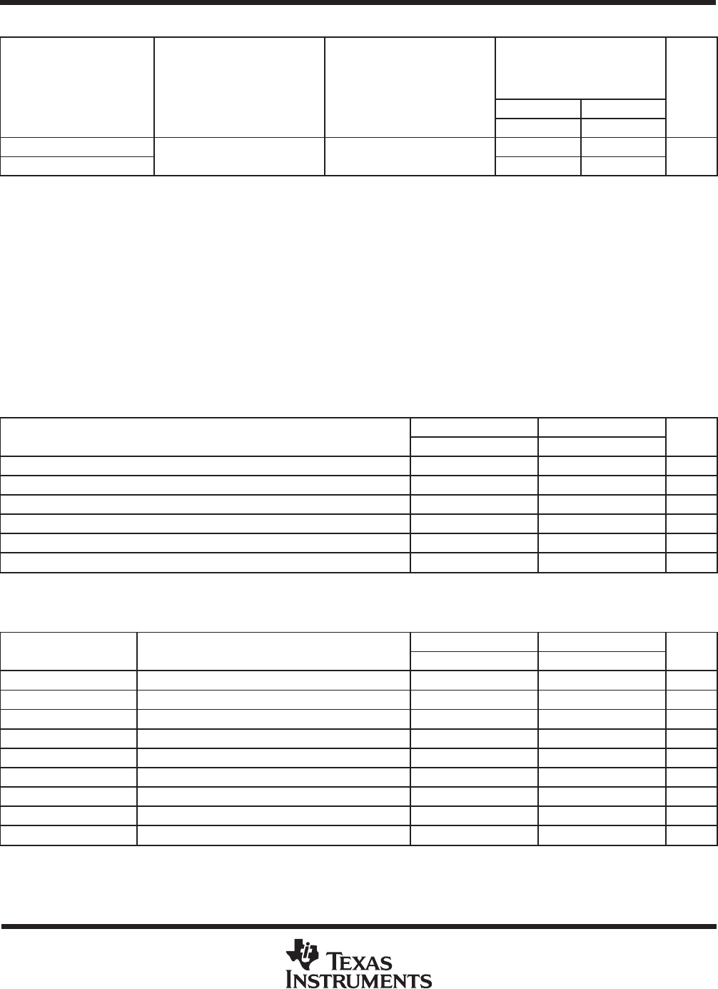
switching characteristics (see Figure 1)
PARAMETER
FROM
TO
V
CC
= 4.5 V to 5.5 V,
C
L
= 50 pF,
R
L
= 500 ,
T
A
= MIN to MAX
UNIT
PARAMETER
SN54ALS10A SN74ALS10A
UNIT
MIN MAX MIN MAX
t
PLH
2 12 2 11
ns
t
PHL
2 12 2 10
ns
For conditions shown as MIN or MAX, use the appropriate value specified under recommended operating conditions.
absolute maximum ratings over operating free-air temperature range (unless otherwise noted)
Supply voltage, V
CC
7 V. . . . . . . . . . . . . . . . . . . . . . . . . . . . . . . . . . . . . . . . . . . . . . . . . . . . . . . . . . . . . . . . . . . . . . . .
Input voltage, V
I
7 V. . . . . . . . . . . . . . . . . . . . . . . . . . . . . . . . . . . . . . . . . . . . . . . . . . . . . . . . . . . . . . . . . . . . . . . . . . . .
Operating free-air temperature range, T
A
: SN54AS10 55°C to 125°C. . . . . . . . . . . . . . . . . . . . . . . . . . . . . . . .
SN74AS10 0°C to 70°C. . . . . . . . . . . . . . . . . . . . . . . . . . . . . . . . . . .
Storage temperature range 65°C to 150°C. . . . . . . . . . . . . . . . . . . . . . . . . . . . . . . . . . . . . . . . . . . . . . . . . . . . . . . .
Stresses beyond those listed under “absolute maximum ratings” may cause permanent damage to the device. These are stress ratings only, and
functional operation of the device at these or any other conditions beyond those indicated under “recommended operating conditions” is not
implied. Exposure to absolute-maximum-rated conditions for extended periods may affect device reliability.
recommended operating conditions
SN54AS10 SN74AS10
UNIT
MIN NOM MAX MIN NOM MAX
UNIT
V
CC
Supply voltage 4.5 5 5.5 4.5 5 5.5 V
V
IH
High-level input voltage 2 2 V
V
IL
Low-level input voltage 0.8 0.8 V
I
OH
High-level output current −2 −2 mA
I
OL
Low-level output current 20 20 mA
T
A
Operating free-air temperature −55 125 0 70 °C
electrical characteristics over recommended operating free-air temperature range (unless
otherwise noted)
PARAMETER
TEST CONDITIONS
SN54AS10 SN74AS10
UNIT
PARAMETER
TEST CONDITIONS
MIN TYP
§
MAX MIN TYP
§
MAX
UNIT
V
IK
V
CC
= 4.5 V, I
I
= −18 mA −1.2 −1.2 V
V
OH
V
CC
= 4.5 V to 5.5 V, I
OH
= −2 mA V
CC
−2 V
CC
−2 V
V
OL
V
CC
= 4.5 V, I
OL
= 20 mA 0.35 0.5 0.35 0.5 V
I
I
V
CC
= 5.5 V, V
I
= 7 V 0.1 0.1 mA
I
IH
V
CC
= 5.5 V, V
I
= 2.7 V 20 20 µA
I
IL
V
CC
= 5.5 V, V
I
= 0.4 V 0.5 0.5 mA
I
O
V
CC
= 5.5 V, V
O
= 2.25 V −30 −112 −30 −112 mA
I
CCH
V
CC
= 5.5 V, V
I
= 0 1.5 2.4 1.5 2.4 mA
I
CCL
V
CC
= 5.5 V, V
I
= 4.5 V 8.1 13 8.1 13 mA
§
All typical values are at V
CC
= 5 V, T
A
= 25°C.
The output conditions have been chosen to produce a current that closely approximates one half of the true short-circuit output current, I
OS
.
123456NEXT