CAT24C01, CAT24C02, CAT24C04, CAT24C08, CAT24C16
http://onsemi.com
15
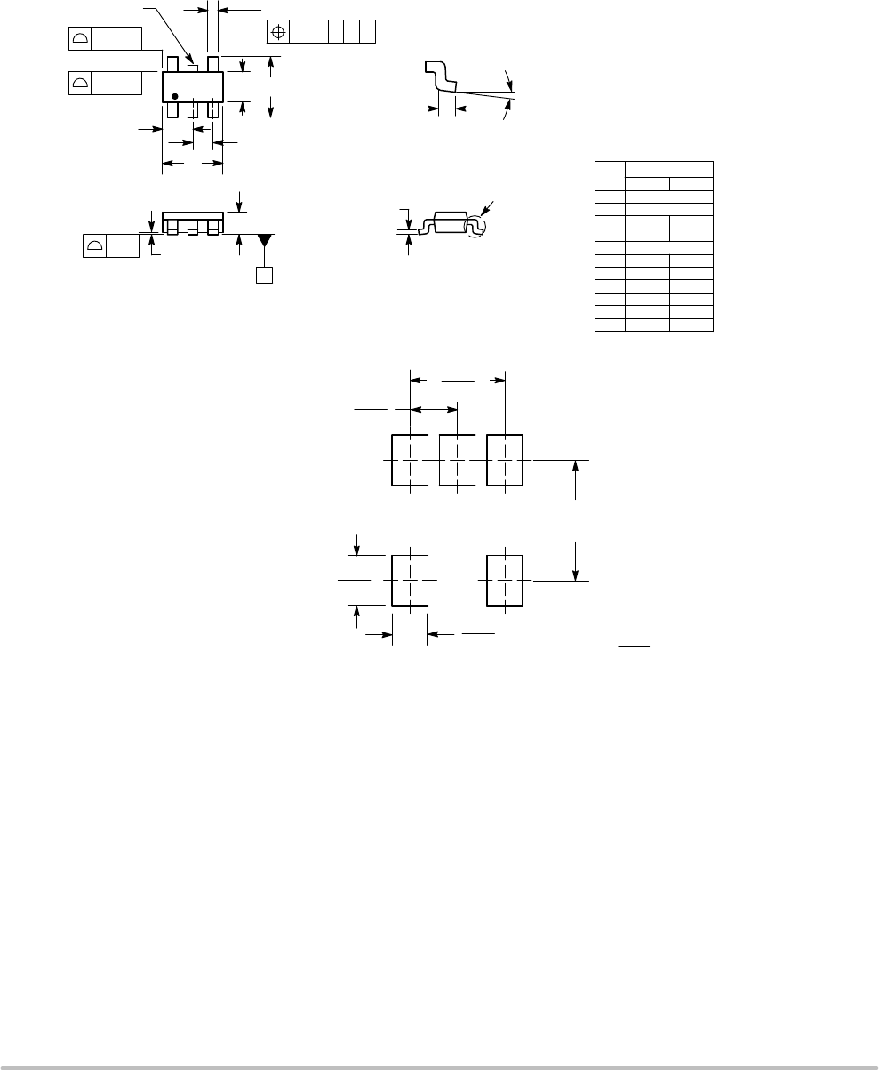
PACKAGE DIMENSIONS
TSOP−5
CASE 483−02
ISSUE H
NOTES:
1. DIMENSIONING AND TOLERANCING PER
ASME Y14.5M, 1994.
2. CONTROLLING DIMENSION: MILLIMETERS.
3. MAXIMUM LEAD THICKNESS INCLUDES
LEAD FINISH THICKNESS. MINIMUM LEAD
THICKNESS IS THE MINIMUM THICKNESS
OF BASE MATERIAL.
4. DIMENSIONS A AND B DO NOT INCLUDE
MOLD FLASH, PROTRUSIONS, OR GATE
BURRS.
5. OPTIONAL CONSTRUCTION: AN
ADDITIONAL TRIMMED LEAD IS ALLOWED
IN THIS LOCATION. TRIMMED LEAD NOT TO
EXTEND MORE THAN 0.2 FROM BODY.
DIM MIN MAX
MILLIMETERS
A 3.00 BSC
B 1.50 BSC
C 0.90 1.10
D 0.25 0.50
G 0.95 BSC
H 0.01 0.10
J 0.10 0.26
K 0.20 0.60
L 1.25 1.55
M 0 10
S 2.50 3.00
123
54
S
A
G
L
B
D
H
C
J
__
0.7
0.028
1.0
0.039
ǒ
mm
inches
Ǔ
SCALE 10:1
0.95
0.037
2.4
0.094
1.9
0.074
*For additional information on our Pb−Free strategy and soldering
details, please download the ON Semiconductor Soldering and
Mounting Techniques Reference Manual, SOLDERRM/D.
SOLDERING FOOTPRINT*
0.20
5X
C AB
T0.10
2X
2X
T0.20
NOTE 5
T
SEATING
PLANE
0.05
K
M
DETAIL Z
DETAIL Z


