Freelance Electronics Components Distributor
Closed Dec 25th-26th
800-300-1968
We Stock Hard to Find Parts

40HF120

Part # 40HF120
Description
Category Microcircuit
Availability Out of Stock
Qty 0
Manufacturer Available Qty
  • Out Of Stock
Request For Quote


Technical Document


DISCLAIMER: The information provided herein is solely for informational purposes. Customers must be aware of the suitability of this product for their application, and consider that variable factors such as Manufacturer, Product Category, Date Codes, Pictures and Descriptions may differ from available inventory.

www.vishay.com For technical questions, contact: ind-modules@vishay.com
Document Number: 93513
4 Revision: 23-Jun-08
40HF(R) Series
Vishay High Power Products
Standard Recovery Diodes,
(Stud Version), 40 A
Fig. 5 - Forward Power Loss Characteristics
Fig. 6 - Forward Power Loss Characteristics
Fig. 7 - Forward Power Loss Characteristics
Average Forward Current (A)
Maximum Average Forward Power Loss (W)
Maximum Allowable Ambient Temperature (°C)
0 40 80 120 160 200
10 K
/W
RthSA = 1 K/W - Delta R
1.5 K/W
2 K/W
3 K/W
5 K/W
7 K/W
0
10
20
30
40
50
60
0 5 10 15 20 25 30 35 40
RMS Limit
Conduction Angle
180°
120°
90°
60°
30°
40HF(R) Series
(100V to 1200V)
Tj = 190°C
Average Forward Current (A)
Maximum Average Forward Power Loss (W)
Maximum Allowable Ambient Temperature (°C)
0 40 80 120 160 200
10 K/W
RthSA = 1 K/W - Delta R
1.5 K/W
2 K/W
3 K/W
5 K/W
7 K/W
0
10
20
30
40
50
60
0 10203040506070
DC
180°
120°
90°
60°
30°
RMS Limit
Conduction Period
40HF(R) Series
(100V to 1200V)
Tj = 190°C
Average Forward Current (A)
Maximum Average Forward Power Loss (W)
Maximum Allowable Ambient Temperature (°C)
0 25 50 75 100 125 150 175 200
1.5 K/W
2 K/W
3 K/W
5 K/W
10 K/W
7 K/W
RthSA = 1 K/W - Delta R
0
5
10
15
20
25
30
35
40
45
50
0 10203040
RMS Limit
Conduction Angle
180°
120°
90°
60°
30°
40HF(R) Series
(1400V, 1600V)
Tj = 160°C
Document Number: 93513 For technical questions, contact: ind-modules@vishay.com
www.vishay.com
Revision: 23-Jun-08 5
40HF(R) Series
Standard Recovery Diodes,
(Stud Version), 40 A
Vishay High Power Products
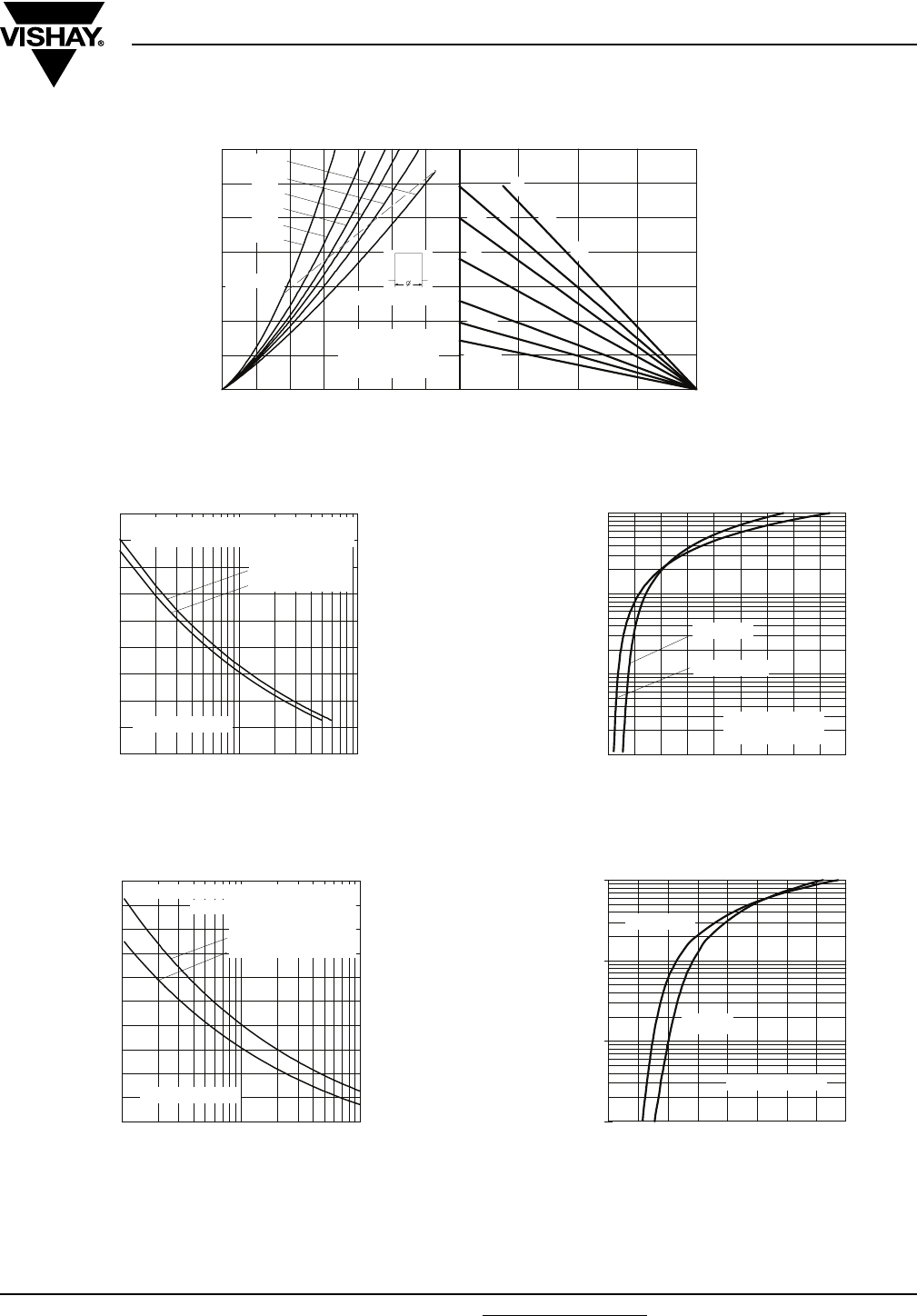
Fig. 8 - Forward Power Loss Characteristics
Fig. 9 - Maximum Non-Repetitive Surge Current
Fig. 10 - Maximum Non-Repetitive Surge Current
Fig. 11 - Forward Voltage Drop Characteristics
(Up To 1200 V)
Fig. 12 - Forward Voltage Drop Characteristics
(For 1400 V/1600 V)
Average Forward Current (A)
Maximum Average Forward Power Loss (W)
Maximum Allowable Ambient Temperature (°C)
04080120160
10 K/W
RthSA = 1 K/W - Delta R
1.5 K/W
2 K/W
3 K/W
5 K/W
7 K/W
0
10
20
30
40
50
60
70
0 10203040506070
DC
180°
120°
90°
60°
30°
RMS Limit
Conduction Period
40HF(R) Series
(1400V, 1600V)
Tj = 160°C
Number Of Equal Amplitude Half Cycle Current Pulses (N)
Peak Half Sine Wave Forward Current (A)
100
150
200
250
300
350
400
450
500
550
110100
40HF(R) Series
Initial Tj = Tj Max.
@ 60 Hz 0.0083 s
@ 50 Hz 0.0100 s
At Any Rated Load Condition And With
Rated Vrrm Applied Following Surge.
Pulse Train Duration (s)
Peak Half Sine Wave Forward Current (A)
100
150
200
250
300
350
400
450
500
550
600
0.01 0.1 1
Maximum Non Repetitive Surge Current
40HF(R) Series
Initial Tj = Tj Max.
No Voltage Reapplied
Rated Vrrm Reapplied
Versus Pulse Train Duration.
Instantaneous Forward Voltage (V)
Instantaneous Forward Current (A)
1
10
100
1000
0.5 1 1.5 2 2.5 3 3.5 4 4.5 5
40HF(R) Series
up to 1200V
Tj = 25°C
Tj = Tj Max.
Instantaneous Forward Voltage (V)
Instantaneous Forward Current (A)
1
10
100
1000
00.511.522.533.54
Tj = 25°C
Tj = Tj Max
40HF (R) Series
www.vishay.com For technical questions, contact: ind-modules@vishay.com
Document Number: 93513
6 Revision: 23-Jun-08
40HF(R) Series
Vishay High Power Products
Standard Recovery Diodes,
(Stud Version), 40 A
Fig. 13 - Thermal Impedance Z
thJC
Characteristics
ORDERING INFORMATION TABLE
Square Wave Pulse Duration (s)
Transient Impedance Z
thJC
(K/W)
0.01
0.1
1
0.0001 0.001 0.01 0.1 1 10
Steady State Value
(DC Operation)
40HF(R) .. Series
1 - 40 = Standard device
41 = Not isolated lead
42 = Isolated lead with silicone sleeve
(red = Reverse polarity)
(blue = Normal polarity)
2 - HF = Standard diode
3 - None = Stud normal polarity (cathode to stud)
R = Stud reverse polarity (anode to stud)
4 - Voltage code x 10 = V
RRM
(see Voltage Ratings table)
5 - None = Stud base DO-203AB (DO-5) 1/4" 28UNF-2
A
M = Stud base DO-203AB (DO-5) M6 x 1
Device code
51324
40 HF R 160 M
LINKS TO RELATED DOCUMENTS
Dimensions http://www.vishay.com/doc?95344
PREVIOUS123NEXT