APPENDIX
71
Trompeter Finish Specification -1
(TFS-1) Notes:
(2) Bright Gold plate on all connector center contacts, pins, sockets, shall be .000050 min - .000070 max thk, Class 1
(3) Thickness is in accordance with MIL-G-45204B, Para 6.3 "Strikes and Underplating"
(4) Copper Alloy articles on which a nickel undercoat is not used shall not be used for continuous service at temperatures above 149°C
(300°F) QQ-S-365, Para. 3.3.5.
(5) For use on Brass and Beryllium Copper body (shell) and accessory components when 500 hour salt spray test is specied. (For test
conditions, refer to MIL-C-38999, Para. 3.16 and 4.7.12.2, [Method 1001.1 of MIL-STD-1344])
(6) Plating thickness variations, critical and noncritical areas must be plated to within specied lower limits, except where
surfaces cannot be contacted by A .75 inch dia ball, noncritical areas total plating thickness may exceed the specied upper limits
by .000150 maximum.
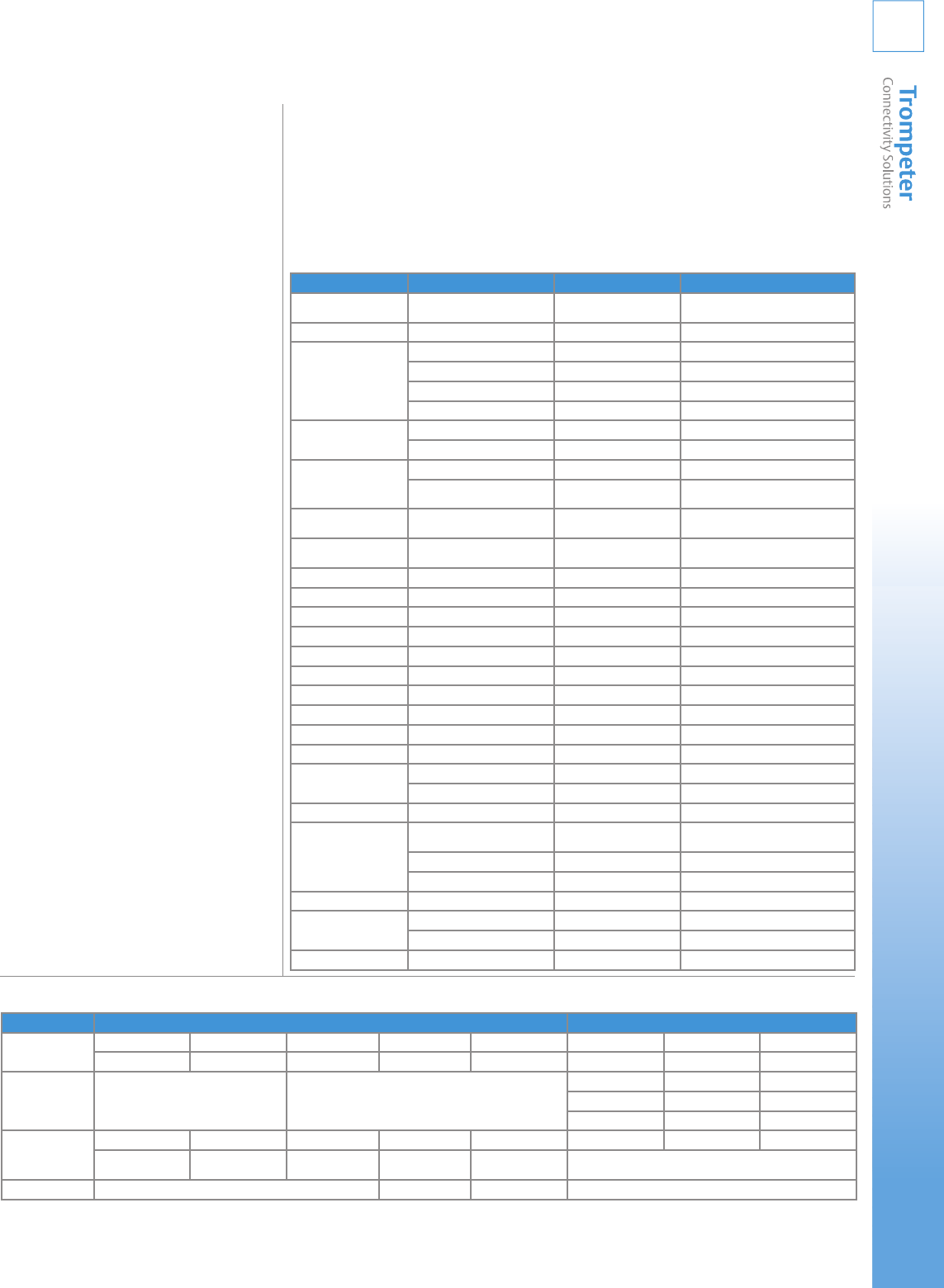
TFS-1: Finish Specifications
TFS-1A
.0001- .0003 max thk Bright Nickel per QQ-N-290, Class1, Form SB (over)
.000080-.000150 thk Bright Copper per MIL-C-14550 (over) .0005 max
Electroless Nickel per AMS-2404C, Class 1 (On Aluminum Only)
TFS-1B
.000020 - .000030 thk Bright Gold2 per MIL-G-45204, Type II, Grade C,
Class3 (over)
.000050-.000180 thk Bright Nickel3 per QQ-N-290, Class1 (over)
.000080-.000150 thk Bright Copper3 per MIL-C-14550
TFS-1D
.0001min - .000120 max thk Electroless Nickel per AMS 2404C (over)
.000080 min - .000150 max thk Bright Copper per MIL-C-14550
TFS-1E
.0002 min -.0003 max thk Bright Electro Tin per MIL-T-10727, Type 1 and
solder test per Para. 4.6.3.1
TFS-1M
4
.000200 min - .000300 max thk Silver per QQ-S-365, Type II (Semi-bright)
Grade A (Chromate post treatment)
(over) .000080 min - .000150 max thk Bright Copper
per MIL-C-14550
TFS-1T
5
.000050 -.000100 Bright Tin per MIL-T-10727, Type I (Electro Deposited)
(over) .000150-.00020 Sulfamate Nickel per MIL-P-27418
(over) .00010-.00150 Copper per MIL-C-14550, Class 4
TFS-1U
5
.00020-.00030 thk Sulfamate Nickel per MIL-P-27418
(over) .000080-.000150 max thk Copper
per MIL-C-14550
TFS-1V
3
.000200-.000300 max thk Silver per QQ-S-365, Type I (Matte), Grade A (over)
.000050-.000180 max thk Sulfamate Nickel per MIL-P-27418, (over)
.000080 min-.000150 max thk Bright Copper
per MIL-C-14550
TFS = Trompeter Finish Specifications
Trompeter General Material/Finish Specifications
Appendix
Materials Alloy or Type FED/MIL Spec. Usage
ABS Moldings Type 2 MIL-STD-1803
L-P-1883B
Looping plug handles, lock pins
Acetal Dupont Delrin L-P-392 Insulators, cases, bushings
Aluminum 2024-T351 QQ-A255/6 Backbars, cases
6061-T6 QQ-A200/8 Stiffener bars
6061-T6 QQ-A250/11 Patch panels
6061-T6511 QQ-A200/8 Backbars, cases
Beryllium Copper 17200 (Bar) ASTM-B-194 Contact & crescent springs
17300 (Flat) ASTM-B-196 &197 Contact sockets, ngersprings, washers
Brass C26000 ASTM-B-36 Ground lugs, washers
C36000 ASTM-B-16 Connector bodies, coupling sleeves, clamp
nuts, hex mtg. nuts, ctr. contact pins, cases
Dupont Acetal Resin #500TL Homopolymer General Purpose w/
1.5% Teon Micropower
Moldings
Fluorinated Ethylene
Propylene
(FEP) ASTM-D-2116 Insulators
Hyon MFA Grade 640 Alternate material dielectric
Loctite 495 (Zinc Iridite per ASTM-B633) QQ-2-325 Type 2 Class 2 Finish
Nylon 6/6 or 6/12 L-P-410A Insulating bushings
Peruoroalkoxy (PFA) ASTM-D-3307 Cable jackets
Phenolic XXX L-P-513 PBE Patch panels, backbars
Phosphor Bronze Alloy 544 ASTM-B-139 Contact springs, lockwashers
Polytetrauoroethylene (PTFE) ASTM-D-1710 Dielectrics, insulators
Polyvinylidene Flouride MIL-I-23053/8 Sealing Sleeves
Rubber Silicone ZZ-R-765 Gaskets, O-rings, sealing members
Solder Sn60, 62, 63, or 96 QQ-S-571
Steel C1010-1018 QQ-S-636 MPN cases
Music Wire ASTM-A228 SAE J178 Tension springs
Steel CRS Type 17-4PH AMS-5643 Tubing
Corrosion Resistant Steel 303 QQ-S-763 Connector bodies, coupling sleeves, hex
mtg. nuts
302 QQ-S-766 Designation strips
301 ASTM-484, A582
Thermo-plastic Polyester Glass Filled MIL-M-24519 Heat resistant molded insulators
Vinyl Clear Rigid-Self ext. ASTM-D-635 Designation strip window
Opaque Rigid-Self ext. ASTM-D-635 Designation strip marking strip
Zinc Alloy #3 ASTM-B-240/B-86 Selected non-functional parts
Connectors Patching
Frequency Range BNC TNC 70 Series 150 Series 450 Series WE Standard WE Miniature RCA Standard
0-4 GHz 0-11 GHz 0-500 MHz 0-500 MHz 0-2 MHz 0-1 GHz 0-1 GHz 0-200 MHz
VSWR 1.30 Max. Not Rated 1.04 @ 75 MHz 1.06 Max. 1.05 @ 50 MHz
1.12 @ 100 MHz - 1.09 @ 100 MHz
1.18 @ 500 MHz - 1.33 @ 500 MHz
Voltage Rating 500 VRMS@ Sea Level 500 VRMS @ Sea Level 400 VRMS @ Sea Level 250 VRMS @ Sea Level 150 VRMS @ Sea Level 500 VRMS @ Sea Level 250 VRMS @ Sea Level 500 VRMS @ Sea Level
125 VRMS @ 70,000 ft. 125 VRMS @ 70,000 ft. 100 VRMS @
70,000 ft.
62.5 VRMS @
70,000 ft.
Not Rated Not Rated
Temperature Range -65°C to 165°C -65°C to 200°C -65°C to 165°C -65°C to165°C


