70HF(R) Series
5
Bulletin I20202 rev. F 01/05
www.irf.com
Fig. 5 - Forward Power Loss Characteristics
Fig. 3 - Current Ratings Characteristics
Fig. 4 - Current Ratings Characteristics
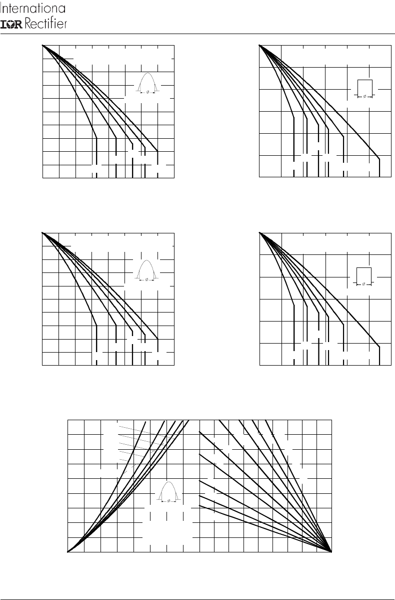
Fig. 1 - Current Ratings Characteristics Fig. 2 - Current Ratings Characteristics
130
140
150
160
170
180
0 1020304050607080
30°
60°
90°
120°
180°
Maximum Allowable Case Temperature (°C)
Conduction Angle
Average Forward Current (A)
70HF(R) Series (100V to 1200V)
R (DC) = 0.45 K/W
thJC
100
110
120
130
140
150
0 1020304050607080
30°
60°
90°
120°
180°
Maxi mum All owable Case Temperature (°C)
Conduction Angle
Average Forward Current (A)
70HF(R) Series (1400V to 1600V)
R (DC) = 0.45 K/W
thJC
0 20 40 60 80 100 120 140 160 180
Maximum Allowable Ambient Temperature (°C)
1
.
5
K
/
W
2
K
/
W
3
K
/
W
5
K
/
W
R
=
0
.
3
K
/
W
-
D
e
l
t
a
R
t
h
S
A
0
.
5
K
/
W
0
.
7
K
/
W
1
K
/
W
4
K
/
W
0
10
20
30
40
50
60
70
80
90
0 1020304050607080
Average Forward Current (A)
RMS Limit
Maximum Average Forward Power Loss (W)
Conduction Angle
180°
120°
90°
60°
30°
70HF(R) Series
(100V to 1200V)
T = 180°C
J
120
130
140
150
160
170
180
0 20406080100120
DC
30°
60°
90°
120°
180°
Maximum Allowable Case Temperature (°C)
Conduction Period
Average Forward Current (A)
70HF(R) Series (100V to 1200V)
R (DC) = 0.45 K/W
thJC
90
100
110
120
130
140
150
0 20406080100120
DC
30°
60°
90°
120°
180°
Maximum Allowable Case Temperature (°C)
Conduction Period
Average Forward Current (A)
70HF(R) Series (1400V to 1600V)
R (DC) = 0.45 K/W
thJC


