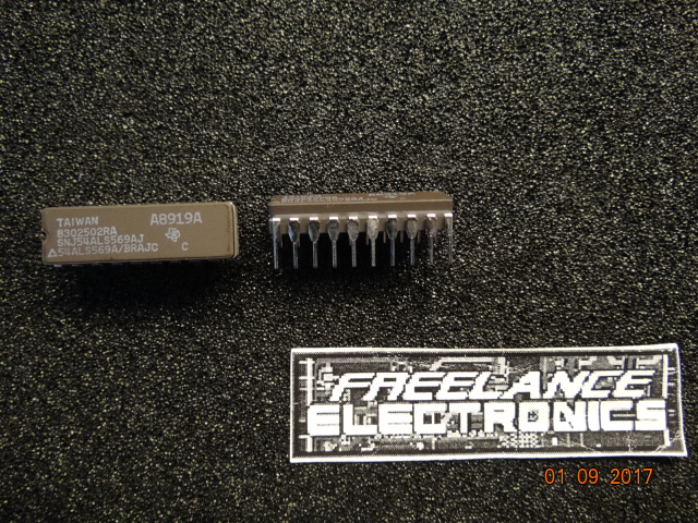
Freelance Electronics Components Distributor
Closed Dec 25th-26th
800-300-1968
We Stock Hard to Find Parts

SNJ54ALS569AJ

Part # SNJ54ALS569AJ
Description Counter Single 4-Bit Binary UP/Down 20-Pin CDIP Tube - Rai
Category IC
Availability In Stock
Qty 148
Qty Price
1 - 6 $36.10616
7 - 17 $28.72081
18 - 36 $27.07962
37 - 79 $25.16490
80 + $22.42958
Manufacturer Available Qty
Texas Instruments
Date Code: 8919
  • Shipping Freelance Stock: 15
    Ships Immediately
Texas Instruments
Date Code: 8911
  • Shipping Freelance Stock: 133
    Ships Immediately


Technical Document


DISCLAIMER: The information provided herein is solely for informational purposes. Customers must be aware of the suitability of this product for their application, and consider that variable factors such as Manufacturer, Product Category, Date Codes, Pictures and Descriptions may differ from available inventory.

SN54ALS569A, SN74ALS568A, SN74ALS569A
SYNCHRONOUS 4-BIT UP/DOWN DECADE AND BINARY COUNTERS
WITH 3-STATE OUTPUTS
SDAS229AAPRIL 1982 – REVISED JANUARY 1995
Copyright 1995, Texas Instruments Incorporated
1
POST OFFICE BOX 655303 DALLAS, TEXAS 75265
3-State Q Outputs Drive Bus Lines Directly
Counter Operation Independent of 3-State
Output
Fully Synchronous Clear, Count, and Load
Asynchronous Clear Is Also Provided
Fully Cascadable
Package Options Include Plastic
Small-Outline (DW) Packages, Ceramic
Chip Carriers (FK), and Standard Plastic (N)
and Ceramic (J) 300-mil DIPs
description
The SN74ALS568A decade counter and
ALS569A binary counters are programmable,
count up or down, and offer both synchronous and
asynchronous clearing. All synchronous functions
are executed on the positive-going edge of the
clock (CLK) input.
The clear function is initiated by applying a low
level to either asynchronous clear (ACLR
) or
synchronous clear (SCLR
). Asynchronous (direct)
clearing overrides all other functions of the device,
while synchronous clearing overrides only the
other synchronous functions. Data is loaded from
the A, B, C, and D inputs by holding load (LOAD
)
low during a positive-going clock transition. The
counting function is enabled only when enable P
(ENP
) and enable T (ENT) are low and ACLR,
SCLR
, and LOAD are high. The up/down (U/D)
input controls the direction of the count. These
counters count up when U/D
is high and count
down when U/D
is low.
A high level at the output-enable (OE
) input forces the Q outputs into the high-impedance state, and a low level
enables those outputs. Counting is independent of OE
. ENT is fed forward to enable the ripple-carry output
(RCO
) to produce a low-level pulse while the count is zero (all Q outputs low) when counting down or maximum
(9 or 15) when counting up. The clocked carry output (CCO
) produces a low-level pulse for a duration equal to
that of the low level of the clock when RCO
is low and the counter is enabled (both ENP and ENT are low);
otherwise, CCO
is high. CCO does not have the glitches commonly associated with a ripple-carry output.
Cascading is normally accomplished by connecting RCO
or CCO of the first counter to ENT of the next counter.
However, for very high-speed counting, RCO
should be used for cascading since CCO does not become active
until the clock returns to the low level.
The SN54ALS569A is characterized for operation over the full military temperature range of –55°C to 125°C.
The SN74ALS568A and SN74ALS569A are characterized for operation from 0°C to 70°C.
1
2
3
4
5
6
7
8
9
10
20
19
18
17
16
15
14
13
12
11
U/D
CLK
A
B
C
D
ENP
ACLR
SCLR
GND
V
CC
RCO
CCO
OE
Q
A
Q
B
Q
C
Q
D
ENT
LOAD
SN54ALS569A ...J PACKAGE
SN74ALS568A, SN74ALS569A . . . DW OR N PACKAGE
(TOP VIEW)
3212019
910111213
4
5
6
7
8
18
17
16
15
14
CCO
OE
Q
A
Q
B
Q
C
B
C
D
ENP
ACLR
SN54ALS569A . . . FK PACKAGE
(TOP VIEW)
A
CLK
U/D
ENT
Q RCO
SCLR
GND
LOAD
V
CC
D
PRODUCTION DATA information is current as of publication date.
Products conform to specifications per the terms of Texas Instruments
standard warranty. Production processing does not necessarily include
testing of all parameters.
SN54ALS569A, SN74ALS568A, SN74ALS569A
SYNCHRONOUS 4-BIT UP/DOWN DECADE AND BINARY COUNTERS
WITH 3-STATE OUTPUTS
SDAS229AAPRIL 1982 – REVISED JANUARY 1995
2
POST OFFICE BOX 655303 DALLAS, TEXAS 75265
FUNCTION TABLE
INPUTS
OPERATION
OE ACLR SCLR LOAD ENT ENP U/D CLK
OPERATION
H X X X X X X X Q outputs disabled
L L X X X X X X Asynchronous clear
L HLXXXXSynchronous clear
L HHLXXX Load
L HHHLLH Count up
L HHHLLL Count down
L H H H H X X X Inhibit count
L H H H X H X X Inhibit count
SN54ALS569A, SN74ALS568A, SN74ALS569A
SYNCHRONOUS 4-BIT UP/DOWN DECADE AND BINARY COUNTERS
WITH 3-STATE OUTPUTS
SDAS229AAPRIL 1982 – REVISED JANUARY 1995
3
POST OFFICE BOX 655303 DALLAS, TEXAS 75265
logic symbols
ENP
CTRDIV10
LOAD
3,5D
3
A
4
B
5
C
6
D
C5/1,4,7,8,+/2,4,7,8–
19
1,7 (CT=9) G9
10
Q
A
Q
B
Q
C
Q
D
U/D
ENT
RCO
2,7 (CT=0) G9
18
6,7,8,9
CCO
EN10
17
M2 [DOWN]
M1 [UP]
1
Z6
2
CLK
G7
12
G8
7
5CT=0
9
M4 [COUNT]
M3 [LOAD]
11
CT=0
8
OE
SCLR
ACLR
16
15
14
13
SN74ALS568A
ENP
CTRDIV16
LOAD
3,5D
3
A
4
B
5
C
6
D
C5/1,4,7,8,+/2,4,7,8–
19
1,7 (CT=15) G9
10
Q
A
Q
B
Q
C
Q
D
U/D
ENT
RCO
2,7 (CT=0) G9
18
6,7,8,9
CCO
EN10
17
M2 [DOWN]
M1 [UP]
1
Z6
2
CLK
G7
12
G8
7
5CT=0
9
M4 [COUNT]
M3 [LOAD]
11
CT=0
8
OE
SCLR
ACLR
16
15
14
13
ALS569A
These symbols are in accordance with ANSI/IEEE Std 91-1984 and IEC Publication 617-12.
1234567NEXT