MSP430x22x2, MSP430x22x4
MIXED SIGNAL MICROCONTROLLER
SLAS504B − JULY 2006 − REVISED JULY 2007
53
POST OFFICE BOX 655303 • DALLAS, TEXAS 75265
POST OFFICE BOX 1443 • HOUSTON, TEXAS 77251−1443
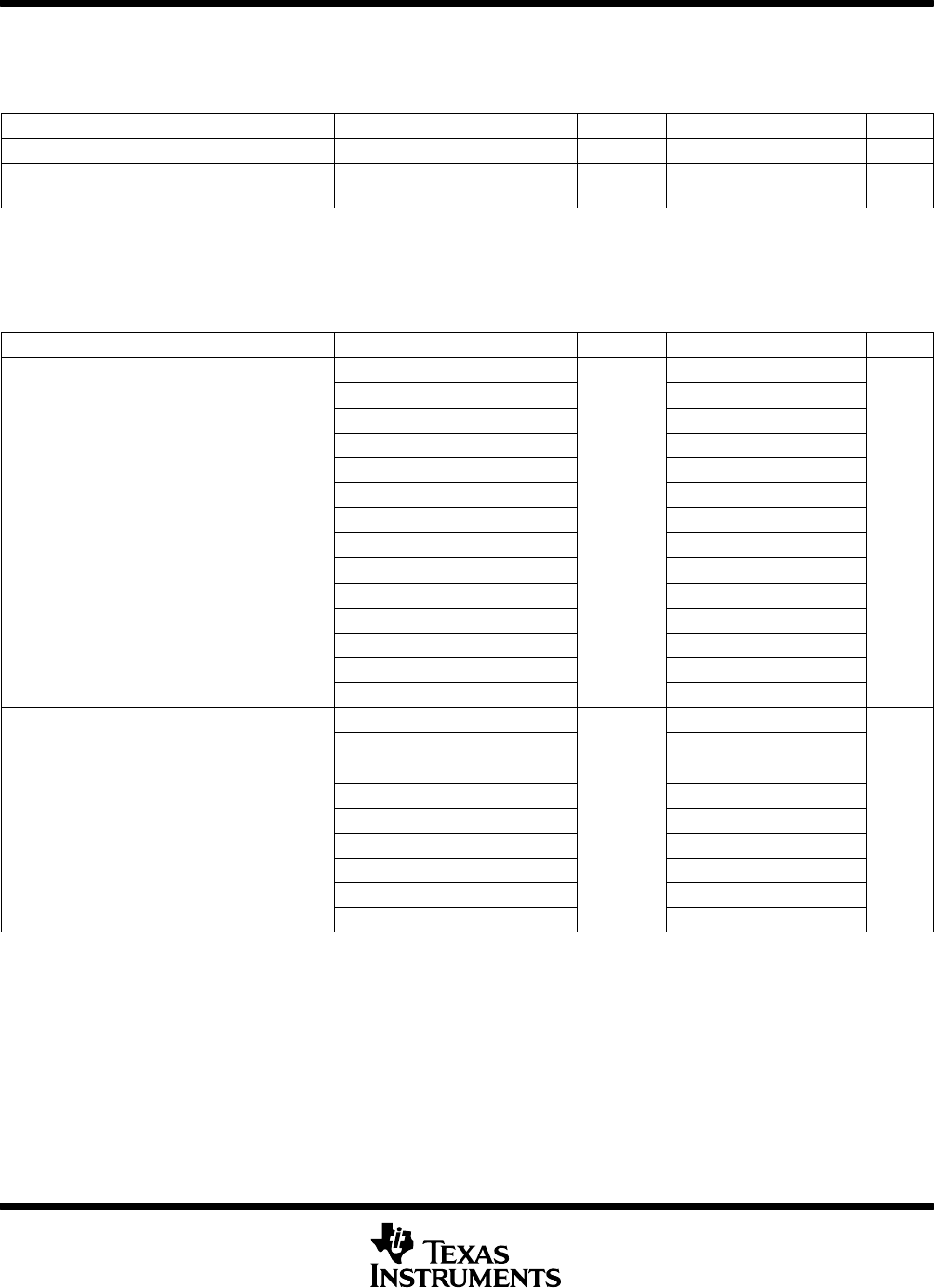
electrical characteristics over recommended ranges of supply voltage and operating free-air
temperature (unless otherwise noted) (continued)
operational amplifier OA feedback network, resistor network (see Note 1) (MSP430x22x4 only)
PARAMETER TEST CONDITIONS VCC MIN TYP MAX UNIT
R
total
Total resistance of resistor string 76 96 128 kΩ
R
unit
Unit resistor of resistor string
(see Note 2)
4.8 6 8 kΩ
NOTES: 1. A single resistor string is composed of 4 R
unit
+ 4 R
unit
+ 2 R
unit
+ 2 R
unit
+ 1 R
unit
+ 1 R
unit
+ 1 R
unit
+ 1 R
unit
= 16 R
unit
= R
total
.
2. For the matching (i.e. the relative accuracy) of the unit resistors on a device refer to the gain and level specifications of the respective
configurations.
operational amplifier OA feedback network,
comparator mode (OAFCx = 3) (MSP430x22x4 only)
PARAMETER TEST CONDITIONS VCC MIN TYP MAX UNIT
OAFBRx = 1, OARRIP = 0 0.245 1/4 0.255
OAFBRx = 2, OARRIP = 0 0.495 1/2 0.505
OAFBRx = 3, OARRIP = 0 0.619 5/8 0.631
OAFBRx = 4, OARRIP = 0 N/A (see Note 1)
OAFBRx = 5, OARRIP = 0 N/A (see Note 1)
OAFBRx = 6, OARRIP = 0 N/A (see Note 1)
OAFBRx = 7, OARRIP = 0
N/A (see Note 1)
V
Level
Comparator level
OAFBRx = 1, OARRIP = 1
2.2 V/ 3 V
0.061 1/16 0.065
V
CC
OAFBRx = 2, OARRIP = 1 0.122 1/8 0.128
OAFBRx = 3, OARRIP = 1 0.184 3/16 0.192
OAFBRx = 4, OARRIP = 1 0.245 1/4 0.255
OAFBRx = 5, OARRIP = 1 0.367 3/8 0.383
OAFBRx = 6, OARRIP = 1 0.495 1/2 0.505
OAFBRx = 7, OARRIP = 1 N/A (see Note 1)
Fast Mode, Overdrive 10 mV 40
Fast Mode, Overdrive 100 mV
4
Fast Mode, Overdrive 500 mV
.
3
Medium Mode, Overdrive 10 mV 60
t
PLH
, t
PHL
Propagation delay
−
−
Medium Mode, Overdrive 100 mV 6
μs
ow−
g
an
g
−
ow
Medium Mode, Overdrive 500 mV 5
Slow Mode, Overdrive 10 mV 160
Slow Mode, Overdrive 100 mV 20
Slow Mode, Overdrive 500 mV 15
NOTES: 1. The level is not available due to the analog input voltage range of the operational amplifier.


