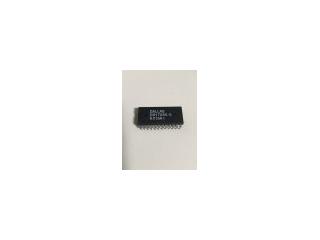
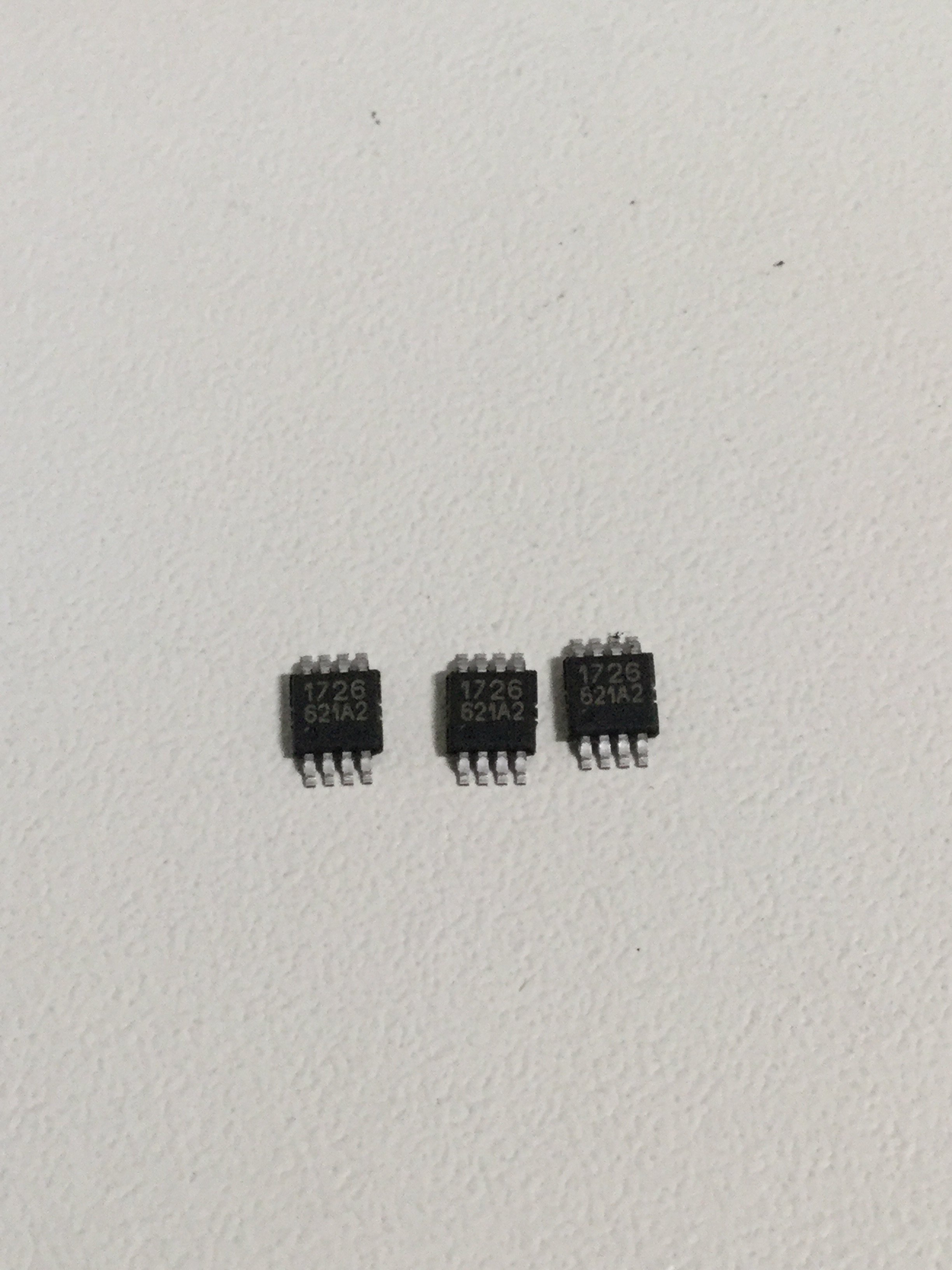
Freelance Electronics Components Distributor
Closed Dec 25th-26th
800-300-1968
We Stock Hard to Find Parts

DS1726U

Part # DS1726U
Description Temp Sensor Digital Serial (3-Wire) 8-Pin uMAX - Rail/Tube
Category IC
Availability In Stock
Qty 194
Qty Price
1 - 40 $2.41267
41 - 81 $1.91917
82 - 122 $1.80950
123 - 162 $1.68156
163 + $1.49878
Manufacturer Available Qty
DALLAS SEMICONDUCTOR
  • Shipping Freelance Stock: 26
    Ships Immediately
MAXIM
Date Code: 0621
  • Shipping Freelance Stock: 166
    Ships Immediately
Military Spec
  • Shipping Freelance Stock: 2
    Ships Immediately


Technical Document


DISCLAIMER: The information provided herein is solely for informational purposes. Customers must be aware of the suitability of this product for their application, and consider that variable factors such as Manufacturer, Product Category, Date Codes, Pictures and Descriptions may differ from available inventory.

1 of 13 06/10/03
FEATURES
§ Temperature Measurements Require No
External Components
§ Measure Temperatures from -55°C to +125°C
(-67°F to +257°F)
§ DS1626: ±0.5°C Accuracy from 0°C to
+70°C
§ DS1726: ±1°C Accuracy from -10°C to
+85°C
§ Output Resolution is User-Selectable to 9, 10,
11, or 12 Bits
§ Wide Power-Supply Range (2.7V to 5.5V)
§ Convert Temperature to Digital Word in
750ms (max)
§ Stand-Alone Thermostat Capability
§ Thermostatic Settings are User-Definable and
Nonvolatile (NV)
§ Data is Read/Written Through a 3-Wire Serial
Interface
§ Available in 8-Pin mMAX/mSOP Package
PIN CONFIGURATION
DESCRIPTION
The DS1626 and DS1726 digital thermometers/thermostats provide temperature measurements and stand-
alone thermostat capability over a -55°C to +125°C range. The DS1626 offers ±0.5°C accuracy from 0°C to
+70°C and the DS1726 has ±1°C accuracy from -10°C to +85°C. The resolution of the measured
temperature is user-selectable from 9 to 12 bits. Communication with the DS1626 and DS1726 is achieved
through a 3-wire serial bus.
The DS1626 and DS1726 offer thermostatic functionality with three dedicated thermostat outputs (T
HIGH
,
T
LOW
, and T
COM
), and over-temperature (T
H
) and under-temperature (T
L
) user-programmable thresholds
stored in on-chip EEPROM. For stand-alone thermostat operation, T
H
and T
L
can be programmed prior to
installation, and the DS1626/DS1726 can be configured to automatically begin taking temperature
measurements at power-up.
Pin descriptions for the DS1626 and DS1726 are provided in Table 2 and user-accessible registers are
summarized in Table 3. A functional diagram is shown in Figure 1.
DS1626/DS1726
High-Precision 3-Wire Digital
Thermometer and Thermostat
www.maxim-ic.com
m
SOP
(
DS1626U
,
DS1726U
)
CLK/
C
N
V
V
DD
T
HIGH
T
LOW
T
COM
GND
R
S
T
D
Q
6
8
7
5
3
1
2
4
See Table 1 for Ordering Information
See Table 2 for Pin Descriptions
APPLICATIONS
§ Thermostatic Controls
§ Industrial Controls
§ Consumer Products
§ Any Space-Constrained Thermally Sensitive
Application
DS1626/DS1726
2 of 13
ORDERING INFORMATION
PART PACKAGE MARKING DESCRIPTION
DS1626U D1626
8-Pin mSOP
DS1626U/T&R D1626
8-Pin mSOP, 3000-Piece Tape-and-Reel
DS1726U D1726
8-Pin mSOP
DS1726U/T&R D1726
8-Pin mSOP, 3000-Piece Tape-and-Reel
Table 2. DETAILED PIN DESCRIPTION
PIN SYMBOL FUNCTION
1DQData Input/Output Pin (Tri-State) for 3-Wire Serial Communication
2CLK/CNV
Clock Input Pin for 3-Wire Serial Communication. Controls temperature
measurements when the DS1626/DS1726 is configured as a stand-alone thermostat
3
RST
Reset Input Pin for 3-Wire Serial Communication
4 GND
Ground Pin
5T
COM
Thermostat Output Pin (Push-Pull) with Programmable Hysteresis
6T
LOW
Thermostat Output Pin (Push-Pull) with T
L
Trip Point
7T
HIGH
Thermostat Output Pin (Push-Pull) with T
H
Trip Point
8V
DD
Supply Voltage. +2.7V to +5.5V Input Power Pin
Table 3. DS1626/DS1726 REGISTER SUMMARY
REGISTER NAME
(USER ACCESS)
SIZE
MEMORY
TYPE
REGISTER CONTENTS
AND POWER-UP/POR STATE
Temperature
(Read Only)
12 Bits SRAM
Measured Temperature (Two’s Complement)
Power-Up/POR State: -60ºC (1100 0100 0000)
T
H
(Read/Write)
12 Bits EEPROM
Upper Alarm Trip Point (Two’s Complement)
Power-Up/POR State: User-Defined.
Initial State from Factory: +15°C (0000 1111 0000)
T
L
(Read/Write)
12 Bits EEPROM
Lower Alarm Trip Point (Two’s Complement)
Power-Up/POR State: User-Defined.
Initial State from Factory: +10°C (0000 1010 0000)
Configuration
(Various Bits are
Read/Write and Read
Only—See Table 5)
1 Byte
SRAM and
EEPROM
Configuration and Status Information (Unsigned)
4MSbs = SRAM and 4LSbs = EEPROM
Power-Up/POR State: 1000XXXX (XXXX = User-
Defined)
Figure 1. DS1626/DS1726 FUNCTIONAL DIAGRAM
T
COM
T
T
LOW
T
H
REGISTER
DIGITAL
COMPARATOR/LOGIC
CONFIGURATION REGISTER AND CONTROL LOGIC
ADDRESS
and
I/O CONTROL
V
DD
CLK/
C
N
V
SD
A
R
ST
GND
TEMPERATURE SENSOR AND DS ADC
TEMPERATURE REGISTER
T
L
REGISTER
DS1626/DS1726
3 of 13
ABSOLUTE MAXIMUM RATINGS*
Voltage on Any Pin Relative to Ground -0.5V to +6.0V
Operating Temperature Range -55°C to +125°C
Storage Temperature Range -55°C to +125°C
Solder Dip Temperature (10s) +260°C
Reflow Oven Temperature +220°C
* These are stress ratings only and functional operation of the device at these or any other conditions
above those indicated in the operation sections of this specification is not implied. Exposure to absolute
maximum rating conditions for extended periods of time may affect reliability.
DC ELECTRICAL CHARACTERISTICS
(V
DD
= 2.7V to 5.5V; T
A
= -55°C to +125°C.)
PARAMETER SYMBOL CONDITIONS MIN TYP MAX UNITS
Supply Voltage V
DD
(Note 1) 2.7 5.5 V
0°C to +70°C,
3.0V £ V
DD
£ 5.5V
±0.5
0°C to +70°C,
2.7V £ V
DD
< 3.0V
±1.25
DS1626
Thermometer Error
(Note 2)
T
ERR
-55°C to +125°C
±2
°C
-10°C to +85°C,
3.0V £ V
DD
£ 5.5V
±1
-10°C to +85°C,
2.7V £ V
DD
< 3.0V
±1.5
DS1726
Thermometer Error
(Note 2)
T
ERR
-55°C to +125°C ±2
°C
Low-Level Input
Voltage
V
IL
(Note 1) -0.5 0.3 x V
DD
V
High-Level Input
Voltage
V
IH
(Note 1) 0.7 x V
DD
V
DD
+ 0.3 V
Input Current each
Input Pin
0.4 < V
I/O
< 0.9 x V
DD
-10 +10 µA
Temperature conversion
-55°C to +85°C
1
Temperature conversion
+85°C to +125°C
1.25
mA
Active Supply
Current (Note 3)
I
DD
E
2
write 400 µA
Input Resistance R
I
RST to GND
DQ, CLK to V
DD
1
MW
Standby Supply
Current
I
STBY
0°C to +70°C (Note 3) 1.5 µA
V
OH
1mA source current 2.4THIGH, TLOW,
TCOM, DQ Output
Logic Voltages
(Note 1)
V
OL
4mA sink current 0.4
V
Thermal Drift (Note 4) ±0.2 °C
12345NEXT