AD680
REV. C
–7–
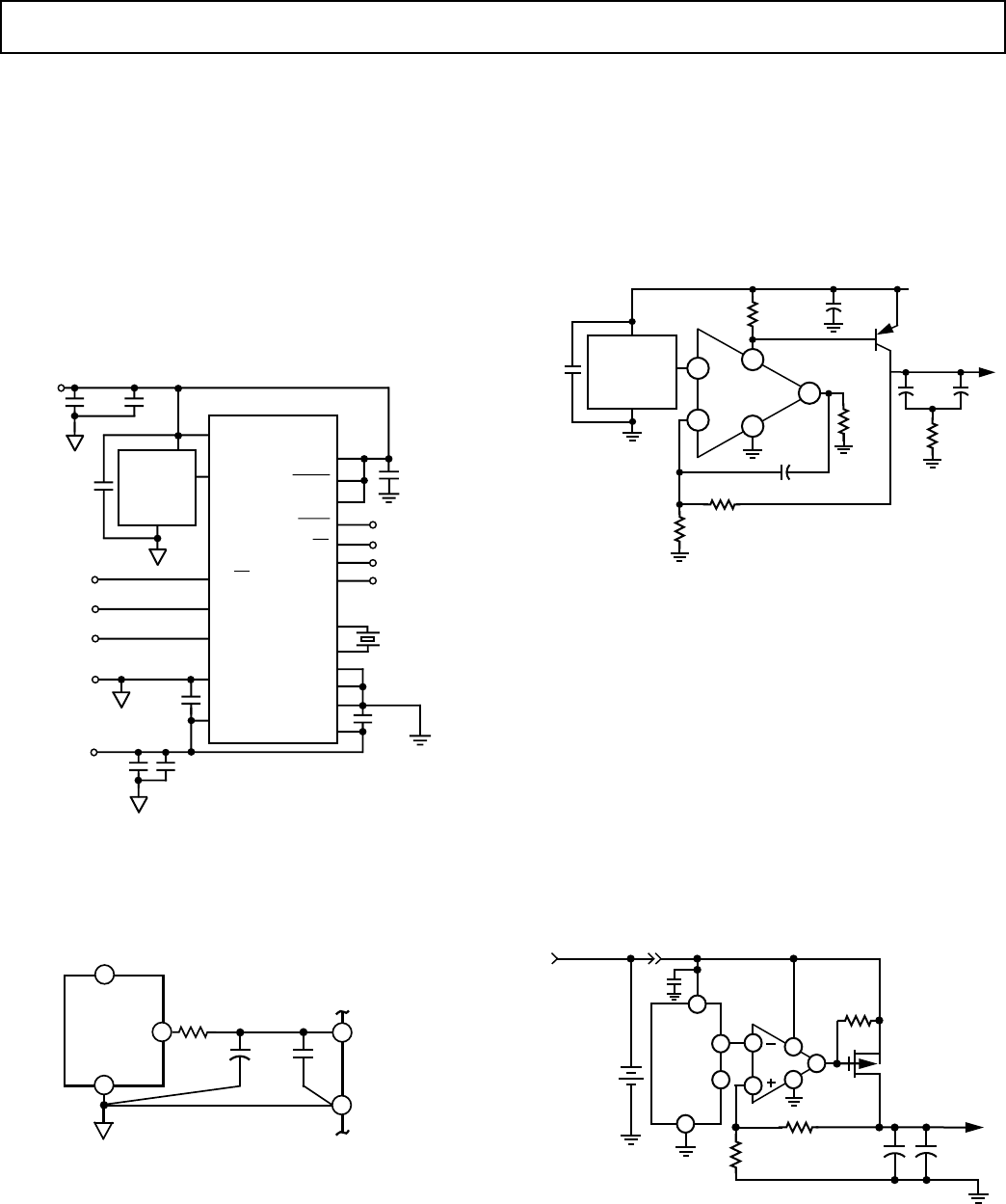
One such ADC that the AD680 is well suitcd for is the
AD7701. Figure 12a shows the AD680 used as the reference for
this converter. The AD7701 is a 16-bit A/D converter with
on-chip digital filtering intended for the measurement of wide
dynamic range, low frequency signals such as those representing
chemical, physical or biological processes. It contains a charge
balancing (sigma-delta) ADC, calibration microcontroller with
on-chip static RAM, a clock oscillator and a serial communica-
tlons port.
This entire circuit runs on ±5 V supplies. The power dissipation
of the AD7701 is typically 25 mW and, when combined with
the power dissipation of the AD680 (1 mW), the entire circuit
consumes just 26 mW of power.
AD7701
MODE
SDATA
SC1
DGND
CLKOUT
CLKIN
AGND
SCLK
SC2
CAL
CS
BP/UP
DV
SS
AV
SS
A
IN
V
REF
AV
DD
DV
DD
SLEEP
RANGE
SELECT
CALIBRATE
ANALOG
INPUT
ANALOG
GROUND
–5V
ANALOG
SUPPLY
0.1µF
SERIAL DATA
SERIAL CLOCK
READ (TRANSMIT)
DATA READY
0.1µF
0.1µF
0.1µF
10µF
DRDY
AD680
V
IN
V
OUT
GND
+5V
ANALOG
SUPPLY
0.1µF10µF
0.1µF
Figure 12a. Low Power, Low Voltage Supply Reference
for the AD7701 16-Bit A/D Converter
Figure 12b shows the AD680 connected to the AD773 high
speed 8-bit ADC. The low pass filter shown minimizes the
AD680’s wideband noise.
AD680
2
GND
V
IN
V
OUT
4
6
REF IN
REF GND
22Ω
10µF
0.1µF
AD773
2
1
Figure 12b. AD680 to AD773 Connection
The AD773’s high impedance reference input allows direct con-
nection to the AD680. Unlike the resistor ladder requirements
of a flash converter the AD773’s single pin, high impedance in-
put can be driven from one low cost, low power reference. The
high impedance input allows multiple AD773’s to be driven
from one AD680 thus minimizing drift errors.
+4.5 V REFERENCE FROM A +5 V SUPPLY
The AD680 can be used to provide a low power, +4.5 V refer-
ence as shown in Figure 13. In addition to the AD680, the cir-
cuit uses a low power op amp and a transistor in a feedback
configuration that provides a regulated +4.5 V output for a
power supply voltage as low as +4.7 V. The high quality tanta-
lum 10 µF capacitor (C1) in parallel with the ceramic 0.1 µF
capacitor (C2) and the 3.9 Ω resistor (R5) ensure a low output
impedance up to around 50 MHz.
3
2
4
6
7
+IN
–IN
V+
V–
OUT
OP-90
CF
0.1µF
R4
3.57k
R5
3.9
C2
0.1µF
+C1
10µF
R1
2k 1%
R2
2.5k
1%
CC
3.3µF
R3
1k
2N2907A
+4.7V TO +15V
AD680
V
OUT
+V
IN
GND
+4.5V
0.1µF
Figure 13. +4.5 V Reference Running from a Single +5 V
Supply
VOLTAGE REGULATOR FOR PORTABLE EQUIPMENT
The AD680 is ideal for providing a stable, low cost and low
power reference voltage in portable equipment power supplies.
Figure 14 shows how the AD680 can be used in a voltage regu-
lator that not only has low output noise (as compared to a
switchmode design) and low power, but also a very fast recovery
after current surges. Some precaution should be taken in the
selection of the output capacitors. Too high an ESR (effective
series resistance) could endanger the stability of the circuit. A
solid tantalum capacitor, 16 V or higher, and an aluminum elec-
trolytic capacitor, 10 V or higher, are recommended for C1 and
C2, respectively. Also, the path from the ground side of C1 and
C2 to the ground side of R1 should be kept as short as possible.
2
3
6
7
2
3
4
4
V
IN
TEMP
GND
AD680
402kΩ
1%
402kΩ
1%
OP-20
++
68µF
TANT
C1
1000µF
ELECT
C2
+5V, 1A
IRF9530
510kΩ
CHARGER
INPUT
+
LEAD-ACID
BATTERY
6V
V
OUT
6
0.1µF
R1
R2
R3
Figure 14. Voltage Regulator for Portable Equipment


