Freelance Electronics Components Distributor
Closed Dec 25th-26th
800-300-1968
We Stock Hard to Find Parts

C1925

Part # C1925
Description BLOCK, JUNCTION - Bulk
Category HARDWARE
Availability In Stock
Qty 2
Qty Price
1 + $24.92401
Manufacturer Available Qty
MAGNUM
  • Shipping Freelance Stock: 2
    Ships Immediately


Technical Document


DISCLAIMER: The information provided herein is solely for informational purposes. Customers must be aware of the suitability of this product for their application, and consider that variable factors such as Manufacturer, Product Category, Date Codes, Pictures and Descriptions may differ from available inventory.

Hardware Description
3-18 AVR STK500 User Guide
1925C–AVR–3/03
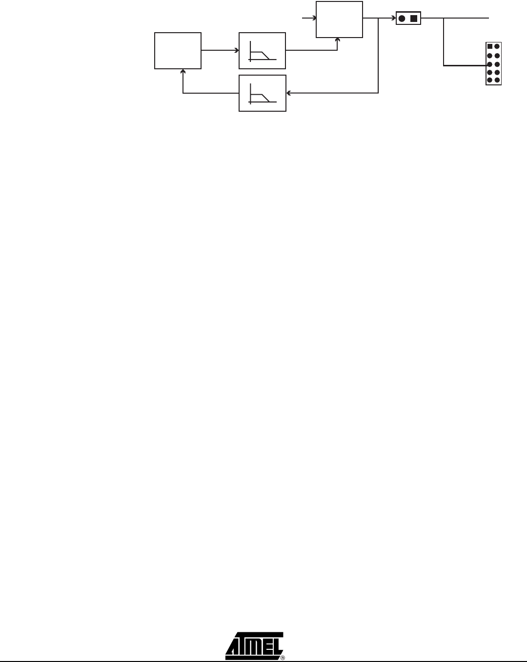
Figure 3-24. Internal AREF Connection
The AVR Studio-controlled analog reference voltage can also be used as an input to the
analog comparator or for ADC measurements on the AVR. AVR’s AREF signal can then
be connected to VTG.
The internal AREF has a short circuit protection. If an AREF value is set up to be higher
than 0.3V and the master microcontroller measures it to be below 0.3V for a duration of
80 ms, the master microcontroller will shut off the AREF. When this happens, the status
LED will blink slowly.
The AREF will also be shut down by the master microcontroller if a short circuit is
detected on VTARGET (in addition to shutting down VTARGET). In this case, the status
LED will blink quickly.
3.8.3 Reset Settings,
RESET
The RESET jumper controls the RESET signal to the STK500. When ISP programming
the target device in the socket, the master microcontroller programs the AVR device
without interfering with the application. When the RESET jumper is mounted, the master
microcontroller controls the RESET signal of the AVR. When the RESET jumper is not
mounted, the RESET signal is disconnected. This is useful for prototype applications
with an external reset system.
The RESET jumper must always be mounted when High-voltage Programming an AVR
device. When using an external reset system, it must allow the reset line to be controlled
by the master microcontroller reset system during programming. The RESET button is
disconnected if the RESET jumper is not mounted. Figure 3-25 explains the RESET
jumper options.
PE1
RST
GND
XT2
VTG
PE0
PE2
REF
XT1
GND
1 2
Master
MCU
AREF
PWM
AREF
PORTE/AUX
Jumper
Voltage
regulator
10 - 15V
VIN
0 - 6V
ADC
Wr
Rd
Hardware Description
AVR STK500 User Guide 3-19
1925C–AVR–3/03
Figure 3-25. RESET Jumper Options
The STK500 master microcontroller controls the RESET signal to the target AVR. The
RESET signal is accessible on the PORTE/AUX header; this pin can also be used for
external RESET signal. Figure 3-26 shows the internal connection of the RESET signal.
Figure 3-26. Internal RESET Connection
Note: During High-voltage Programming, STK500 applies 12V to the AVR’s RESET
line. Thus, an external reset circuit not capable of handling this must be discon-
nected before High-voltage Programming the AVR.
AREF
RESET
XTAL1
Jumper Mounted
AREF
RESET
XTAL1
Jumper not Mounted
On-board RESET Signal Disconnected
On-board RESET Signal Connected (default)
PE1
RST
GND
XT2
VTG
PE0
PE2
REF
XT1
GND
1 2
Master
MCU
RESET NET
0V - VTG - 12V
RESET
CIRCUIT
RESET
PORTE/AUX
RESET
Jumper
Hardware Description
3-20 AVR STK500 User Guide
1925C–AVR–3/03
When connected to an external system, there is often an external pull-up resistor con-
nected to the reset line. A typical reset connection is shown in Figure 3-27.
Figure 3-27. External Reset Connection
If the external pull-up resistor is too low (<4.7 k), STK500 will not be able to pull the
RESET line low.
3.8.4 Clock Settings,
XTAL1 and OSCSEL
STK500 includes several clock options for the target AVR. Setting the jumpers XTAL1
and OSCSEL controls the clock selections. OSCSEL determines what signal to route to
the XTAL1 pin of the AVR.
When the XTAL1 jumper is connected, the STK500 internal clock system is used as
main clock to the target AVR. When XTAL1 jumper is not mounted, the internal clock
system is disconnected. This allows external clock signals or crystals to be used as tar-
get clock source for the AVR. Figure 3-28 illustrates the XTAL1 jumper option.
Figure 3-28. XTAL1 Jumper Options
When the XTAL1 jumper is not mounted, an external clock source or crystal can be con-
nected to the PORTE header. This is shown in Figure 3-30.
R (4.7 kohm)
C (10 nF)
RESET
AREF
RESET
XTAL1
OSCSEL
Jumper Mounted
On-board XTAL1 Signal Connected (Default)
AREF
RESET
XTAL1
OSCSEL
Jumper not Mounted
On-board XTAL1 Signal Disconnected
PREVIOUS345678910111213141516NEXT