Closed Dec 25th-26th
800-300-1968
We Stock Hard to Find Parts
My Account
|
My Orders
|
My Cart
Questions?
(800) 300-1968
Register
(current)
My Account
(current)
My Orders
(current)
My Cart
(current)
Categories
(current)
Manufacturers
Request a Quote
Sell Your Excess
Consignment
Quality Assurance
PT6425
Part #
PT6425
Description
5V-3.3V
Category
VOLTAGE REGULAT
Availability
In Stock
Qty
1
Manufacturer
Available
Qty
Military Spec
Date Code: 0151
Freelance Stock:
1
Ships Immediately
Request For Quote
Request For Quote
Related Items
II
VOLTAGE REGULAT
1122VC
Texas Instruments
VOLTAGE REGULAT
1136VC
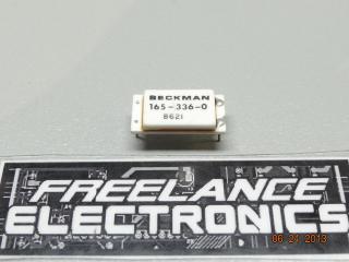
BECKMAN INDUSTRIAL
VOLTAGE REGULAT
165-336-0
$8.00930
Military Spec
VOLTAGE REGULAT
1950114-100
ON Semiconductor
VOLTAGE REGULAT
1SMB5949BT3G
$0.04888
REPUBLIC MFG.
VOLTAGE REGULAT
2-2262-3