Freelance Electronics Components Distributor
Closed Dec 25th-26th
800-300-1968
We Stock Hard to Find Parts

78L05ACP

Part # 78L05ACP
Description
Category TRANSISTOR
Availability In Stock
Qty 39
Qty Price
1 + $0.76534
Manufacturer Available Qty
Motorola Corp
  • Shipping Freelance Stock: 39
    Ships Immediately


Technical Document


DISCLAIMER: The information provided herein is solely for informational purposes. Customers must be aware of the suitability of this product for their application, and consider that variable factors such as Manufacturer, Product Category, Date Codes, Pictures and Descriptions may differ from available inventory.

MC78L00A Series, NCV78L00A
http://onsemi.com
7
P
D
, POWER DISSIPATION (mW)
I
IB
, INPUT BIAS CURRENT (mA)
I
IB
, INPUT BIAS CURRENT (mA) V
O
, OUTPUT VOLTAGE (V)
Figure 3. Dropout Characteristics Figure 4. Dropout Voltage versus
Junction Temperature
Figure 5. Input Bias Current versus
Ambient Temperature
Figure 6. Input Bias Current
versus Input Voltage
Figure 7. Maximum Average Power Dissipation versus
Ambient Temperature − TO−92 Type Package
V
I
, INPUT VOLTAGE (V)
0 2.0 4.0 6.0 8.0 10
, INPUT/OUTPUT DIFFERENTIAL VOLTAGE (V)
IO
T
J
, JUNCTION TEMPERATURE (°C)
0 25 50 75 100 125
−VV
Dropout of Regulation is
defined as when
V
O
= 2% of V
O
T
A
, AMBIENT TEMPERATURE (°C)
0 25 50 75 100 125
V
I
, INPUT VOLTAGE (V)
0 5.0 10 15 20 25 30 35 40
T
A
, AMBIENT TEMPERATURE (°C)
25 50 75 100 125 150
No Heatsink
8.0
6.0
4.0
2.0
0
2.5
2.0
1.5
1.0
0.5
0
4.2
4.0
3.8
3.6
3.4
3.2
3.0
0
5.0
4.0
3.0
2.0
1.0
0
10,000
1000
100
10
MC78L05AC
V
out
= 5.0 V
T
J
= 25°C
MC78L05AC
V
out
= 5.0 V
I
O
= 40 mA
T
J
= 25°C
R
JA
= 200°C/W
P
D(max)
to 25°C = 625 mW
I
O
= 1.0 mA
I
O
= 40 mA
I
O
= 100 mA
I
O
= 70 mA
I
O
= 1.0 mA
I
O
= 40 mA
MC78L05AC
V
I
= 10 V
V
O
= 5.0 V
I
O
= 40 mA
30
50
70
90
110
130
150
0.4
0.8
1.2
1.6
2.0
2.4
2.8
02030504010
L, LENGTH OF COPPER (mm)
170
3.2
R
JA
P
D
R , THERMAL RESISTANCE
JAθ
JUNCTION-TO-AIR ( C/W)°
, MAXIMUM POWER DISSIPATION (W)
2.0 oz.
Copper
Graph represents symmetrical layout
3.0 mmL
L
Figure 8. SOIC−8 Thermal Resistance and Maximum
Power Dissipation versus P.C.B. Copper Length
P
D(max)
for T
A
= 50°C
MC78L00A Series, NCV78L00A
http://onsemi.com
8
APPLICATIONS INFORMATION
Design Considerations
The MC78L00A Series of fixed voltage regulators are
designed with Thermal Overload Protection that shuts
down the circuit when subjected to an excessive power
overload condition. Internal Short Circuit Protection limits
the maximum current the circuit will pass.
In many low current applications, compensation
capacitors are not required. However, it is recommended
that the regulator input be bypassed with a capacitor if the
regulator is connected to the power supply filter with long
wire lengths, or if the output load capacitance is large. The
input bypass capacitor should be selected to provide good
high−frequency characteristics to insure stable operation
under all load conditions. A 0.33 F or larger tantalum,
mylar, or other capacitor having low internal impedance at
high frequencies should be chosen. The bypass capacitor
should be mounted with the shortest possible leads directly
across the regulators input terminals. Good construction
techniques should be used to minimize ground loops and
lead resistance drops since the regulator has no external
sense lead. Bypassing the output is also recommended.
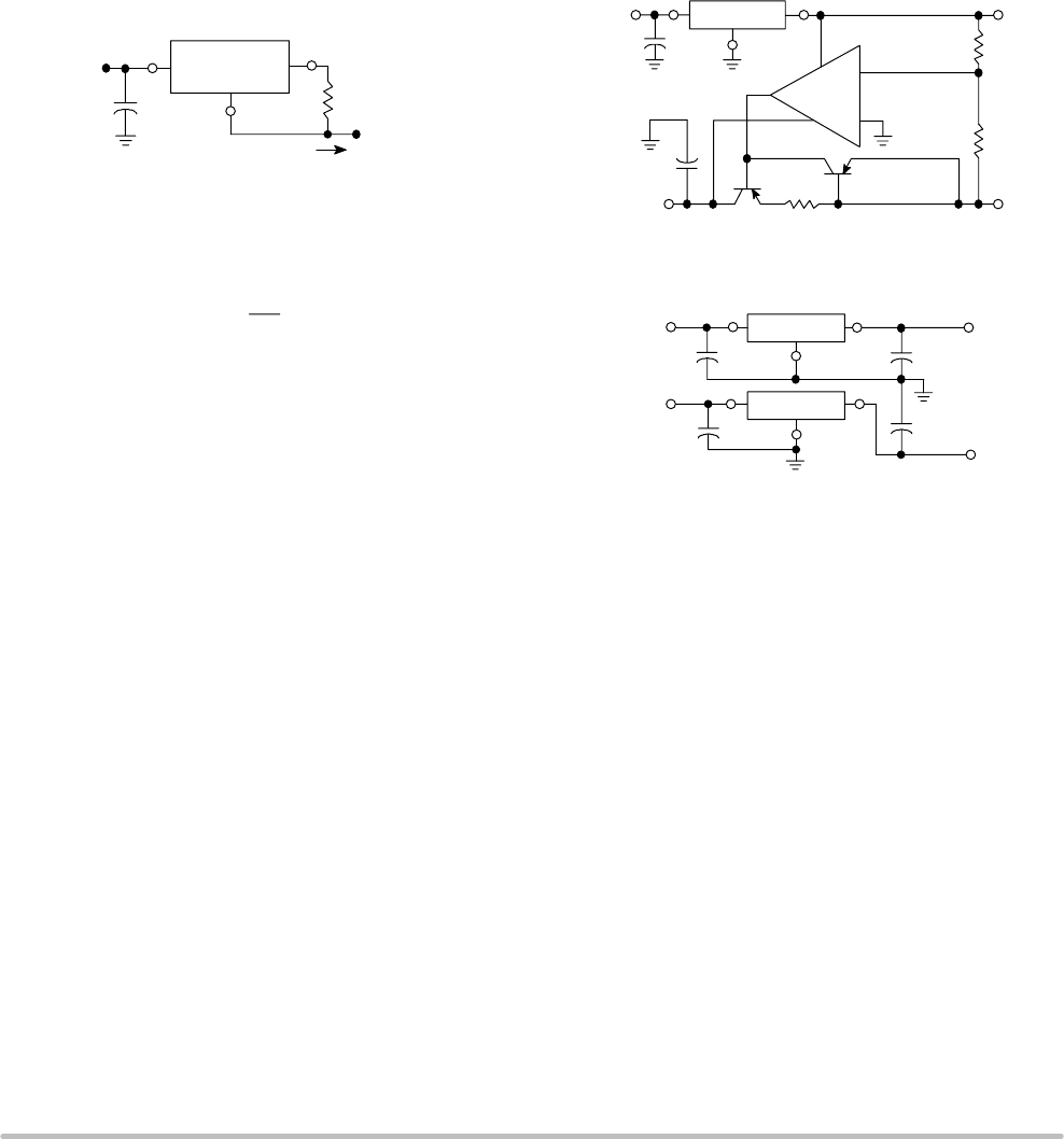
Figure 9. Current Regulator
Figure 10. ± 15 V Tracking Voltage Regulator
The MC78L00 regulators can also be used as a current source
when connected as above. In order to minimize dissipation the
MC78L05C is chosen in this application. Resistor R determines
the current as follows:
For example, a 100 mA current source would require R to be a
50, 1/2 W resistor and the output voltage compliance would be
the input voltage less 7 V.
I
O
=
5.0 V
+ I
B
I
IB
= 3.8 mA over line and load changes
Input
0.33F
R
I
O
MC78L05A
Constant
Current to
Grounded Load
+
MC1741
+20V
0.33F
MC78L15A +V
O
10k
10k
−V
O
7
6
2
3
4
6.5
20V
MPS A70
MPS U55
0.33F
0.33F
+V
I
−V
I
MC78LXXA
MC79LXXA
+V
O
−V
O
0.33F
0.1F
0.1F
R
Figure 11. Positive and Negative Regulator
MC78L00A Series, NCV78L00A
http://onsemi.com
9
ORDERING INFORMATION
Device Output Voltage
Operating
Temperature Range
Package Shipping
MC78L05ABD SOIC−8 98 Units/Rail
MC78L05ABDG SOIC−8 98 Units/Rail
MC78L05ABDR2 SOIC−8 2500 Tape & Reel
MC78L05ABDR2G SOIC−8
(Pb−Free)
2500 Tape & Reel
NCV78L05ABDR2* SOIC−8 2500 Tape & Reel
MC78L05ABP TO−92 2000 Units/Bag
MC78L05ABPG
T
J
=−
40
°
to +125
°
C
TO−92
(Pb−Free)
2000 Units/Bag
MC78L05ABPRA
T
J
= −
40°
to
+125°C
TO−92 2000 Tape & Reel
MC78L05ABPRAG TO−92
(Pb−Free)
2000 Tape & Reel
MC78L05ABPRE TO−92 2000 Tape & Reel
MC78L05ABPREG TO−92
(Pb−Free)
2000 Tape & Reel
MC78L05ABPRM TO−92 2000 Ammo Pack
MC78L05ABPRMG TO−92
(Pb−Free)
2000 Ammo Pack
MC78L05ACD SOIC−8 98 Units/Rail
MC78L05ACDG
5.0 V
SOIC−8
(Pb−Free)
98 Units/Rail
MC78L05ACDR2 SOIC−8 2500 Tape & Reel
MC78L05ACDR2G SOIC−8
(Pb−Free)
2500 Tape & Reel
MC78L05ACP TO−92 2000 Units/Bag
MC78L05ACPG TO−92
(Pb−Free)
2000 Units/Bag
MC78L05ACPRA TO−92 2000 Tape & Reel
MC78L05ACPRAG
T
J
= 0° to +125°C
TO−92
(Pb−Free)
2000 Tape & Reel
MC78L05ACPRE TO−92 2000 Tape & Reel
MC78L05ACPREG TO−92
(Pb−Free)
2000 Tape & Reel
MC78L05ACPRM TO−92 2000 Ammo Pack
MC78L05ACPRMG TO−92
(Pb−Free)
2000 Ammo Pack
MC78L05ACPRP TO−92 2000 Ammo Pack
MC78L05ACPRPG TO−92
(Pb−Free)
2000 Ammo Pack
*NCV78L05A: T
low
= −40°C, T
high
= +125°C. Guaranteed by design. NCV prefix is for automotive and other applications requiring site and change
control.
For information on tape and reel specifications, including part orientation and tape sizes, please refer to our Tape and Reel Packaging
Specifications Brochure, BRD8011/D.
PREVIOUS123456NEXT