S
222
ACCESSORIES
S Relay Socket,
S-PS
Specifications
(Note: Don't insert or remove relays while in the energized condition.)
Breakdown voltage 1,500 Vrms between terminals
Insulation resistance More than 100 M
Ω
between terminals at 500 V DC Mega
Heat resistance 150
±
3
°
C (302
±
5.4°F) for 1 hour.
Maximum continuous current 4 A
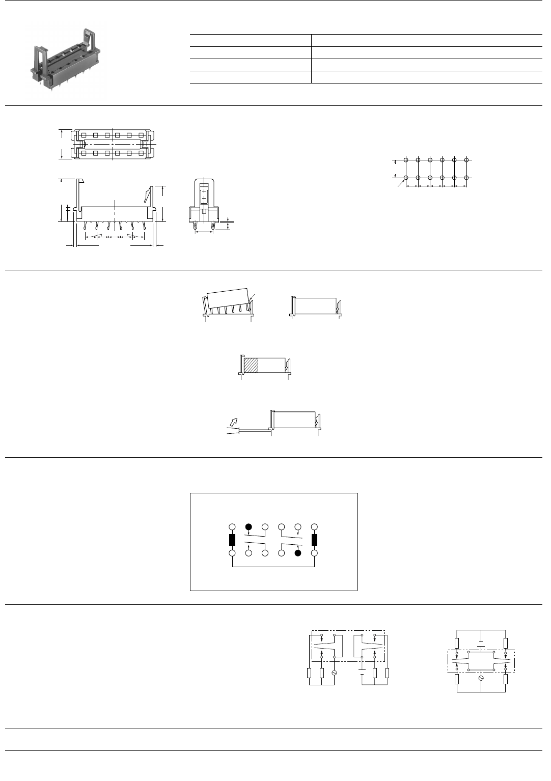
Dimensions
PC board pattern (Copper-side view)
12.4±0.6
.488±.024
18.3±0.6
.720±.024
15.5±0.6
.610±.024
3.4±0.3
.134±.012
0.4±0.1
.016±.004
1.2±0.3
.047±.012
4.85±0.3
.191±.012
5.08±0.3
.200±.012
32.4±0.6
1.276±.024
1.5±0.3
.059±.012
1.5±0.3
.059±.012
7.62±0.3
.300±.012
Terminal width: 1.3 .051
Terminal thickness: 1.2 .047
7.6
.299
5.08
.200
5.08
.200
5.08
.200
5.08
.200
5.08
.200
12-1.6 DIA. HOLE
12-.063 DIA. HOLE
mm inch
Inserting and removing method
Inserting method: Insert the relay as
shown in Fig. 1 unit the rib of the relay
snaps into the clip of the socket.
Rib
Fig. 1
Removing method:
(1) Remove the relay straight from the
socket holding the shaded portion of the
relay as shown in Fig. 2.
Fig. 2
(2) When sockets are mounted in close
proximity, use a slotted screw driver as
shown in Fig. 3.
Fig. 3
NOTES
1. Special use of 2 coil latching types: 2
ways can be considered if 2 coil latching
types are used as 1 coil latching types.
(A) Reverse polarity is applied to the set
coil of 2 coil latching type.
(B) By shorting terminals 12 and 7, apply
plus to 1, minus to 6 at set and plus to 6,
minus to 1 at reset. Applied coil voltage
should be the same as the nominal. Oper-
ating power will be reduced to one-half.
Reset position of 2a2b type 2. Soldering operations should be accom-
plished as quick as possible; within 10
seconds at 250°C 482°F solder tempera-
ture or 3 seconds at 350°C 662°F. The
header portion being sealed with epoxy
resin, undue subjection to heat may
cause loss of seal. Solder should not be
permitted to remain on the header.
123456
12 11 10 9 8 7
-
+
CAUTIONS FOR USE
Based on regulations regarding insulation distance, there is a re-
striction on same-channel load connections between terminals
No. 2, 3 and 4, 5, as well as between No. 8, 9 and 10, 11. See the
figure below for an example.
4
2
5
3
10
9
4
8
11
5
23
9
8
11
• Between 2, 3 and 4, 5:
• Between 10, 11 and 8, 9:
same channels, therefore possible
same channels, therefore possible
• Between 2, 3 and 4, 5:
• Between 10, 11 and 8, 9:
different channels, therefore not possible
different channels, therefore not possible
10
No good Good
For Cautions for Use, see Relay Technical Information (Page 48 to 76).
9/1/2000 All Rights Reserved, © Copyright Matsushita Electric Works, Ltd.
Go To Online Catalog


