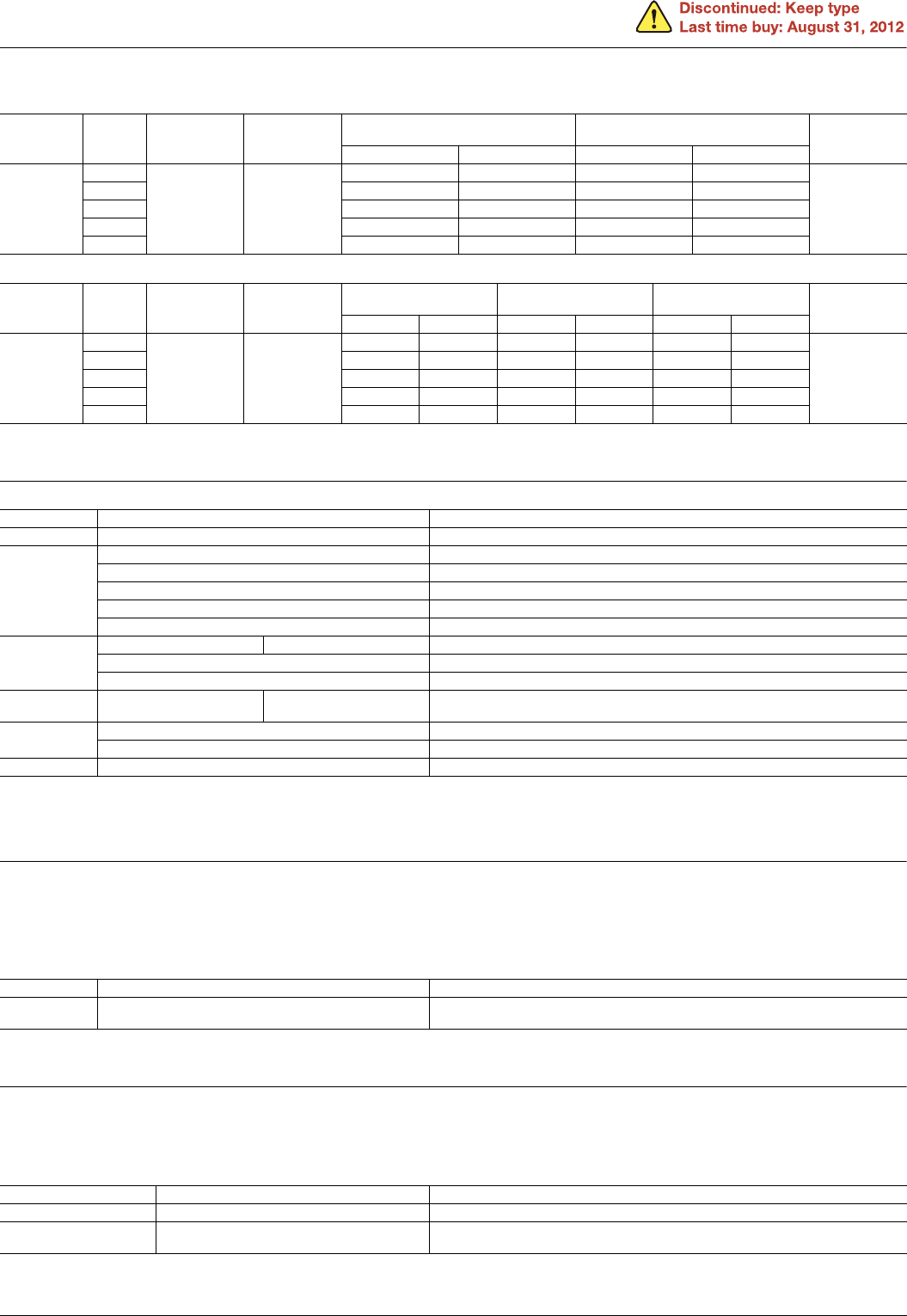
Freelance Electronics Components Distributor
Closed Dec 25th-26th
800-300-1968
We Stock Hard to Find Parts

HC4-H-DC6V

Part # HC4-H-DC6V
Description RELAY GENERAL PURPOSE 4PDT 5A6V
Category RELAY
Availability In Stock
Qty 1
Qty Price
1 + $8.84570
Manufacturer Available Qty
Aromat
  • Shipping Freelance Stock: 1
    Ships Immediately


Technical Document


DISCLAIMER: The information provided herein is solely for informational purposes. Customers must be aware of the suitability of this product for their application, and consider that variable factors such as Manufacturer, Product Category, Date Codes, Pictures and Descriptions may differ from available inventory.

HC
3. Keep relay
1) Coil data
(1) AC coils (50/60Hz)
(2) DC coils
Notes: 1. The allowable coil resistance range is ±10% when within 1,000 and ±15% when. 1,000 or higher.
2. The maximum applied voltage is the maximum voltage fluctuation value for the coil power supply. This value is not a permissible value for continuous operation.
(This value differs depending on the ambient temperature. Please contact us for details.)
2) Specifications
Notes: *1. This value can change due to the switching frequency, environmental conditions and desired reliability level, therefore it is recommended to check this with the
actual load.
*2. Other specifications are same as standard type HC relay. Please see the standard type HC relay.
*3. Please maintain (reset) the relay more than once a year. Leaving it in the set position for long periods of time will cause the magnet to attenuate over the years.
This will decrease the holding power and cause failure of the set position.
4. With diode type (For DC)
1) Coil data
Same coil data as HC relay standard type for DC. Please refer to standard type information.
Please connect DC coil type built-in diode correctly by verifying the coil polarity.
2) Specifications
Notes: Other specifications are same as standard type HC relay. Please see the standard type HC relay.
* The upper limit of the ambient temperature is the maximum temperature that can satisfy the coil temperature rise value. Refer to Usage, transport and storage
conditions in NOTES.
5. With CR circuit type
1) Coil data
Same coil data as HC relay standard type for AC. Please refer to standard type information.
2) Specifications
Notes: Other specifications are same as standard type HC relay. Please see the standard type HC relay.
* The upper limit of the ambient temperature is the maximum temperature that can satisfy the coil temperature rise value. Refer to Usage, transport and storage
conditions in NOTES.
Contact
arrangement
Nominal
coil
voltage
Set voltage
(at 20°C 68°F)
Reset voltage
(at 20°C 68°F)
Nominal operating current
[±10%] (at 20°C 68°F)
Nominal operating power
Max. applied
voltage
(at 50°C 122°F)
Set coil Reset coil Set coil Reset coil
2 Form C
6V AC
80%V or less of
nominal voltage
(Initial)
80%V or less of
nominal voltage
(Initial)
206mA 103mA 1.23VA 0.62VA
110%V of
nominal voltage
12V AC 100mA 52mA 1.20VA 0.62VA
24V AC 51mA 21.4mA 1.22VA 0.51VA
48V AC 25.2mA 18.5mA 1.20VA 0.88VA
100V AC 13.3mA 7.1mA 1.33VA 0.71VA
Contact
arrangement
Nominal
coil
voltage
Set voltage
(at 20°C 68°F)
Reset voltage
(at 20°C 68°F)
Nominal operating current
[±10%] (at 20°C 68°F)
Coil resistance
[±10%] (at 20°C 68°F)
Nominal operating power
Max. applied
voltage
(at 50°C 122°F)
Set coil Reset coil Set coil Reset coil Set coil Reset coil
2 Form C
6V DC
80%V or less of
nominal voltage
(Initial)
80%V or less of
nominal voltage
(Initial)
207mA 107mA 29 56 1.24W 0.64W
110%V of
nominal voltage
12V DC 100mA 52.2mA 120 230 1.20W 0.63W
24V DC 51.1mA 25.5mA 470 941 1.23W 0.61W
48V DC 25.3mA 13.7mA 1,897 3,504 1.21W 0.66W
100V DC 15.6mA 5.8mA 6,410 17,241 1.56W 0.58W
Characteristics Item Specifications
Contact Contact resistance (Initial) Max. 50 m (By voltage drop 6 V DC 1A)
Rating
Nominal switching capacity (resistive load) 3A 250V AC
Max. switching power (resistive load) 750VA
Max. switching current 3A
Nominal operating power Set coil: 1.20VA to 1.33VA; Reset coil: 0.51VA to 0.88VA
Min. switching capacity (Reference value)*
1
100µA 100mV DC
Electrical
characteristics
Breakdown voltage (Initial) Between contact and coil 1,500 Vrms for 1min.
Temperature rise (coil) Set coil: Max. 80°C 176°F; Reset coil: Max. 50°C 122°F (at nominal coil voltage)
Set time/Reset time (at 20°C 68°F) Approx. 20ms/30ms (at nominal coil voltage)
Mechanical
characteristics
Shock resistance Functional Min. 98m/s
2
(Half-wave pulse of sine wave: 11 ms; detection time: 10µs.)
Expected life
Mechanical Min. 10
7
(at 180 times/min.)
Electrical Min. 2×10
5
rated load (at 20 times/min.)
Conditions Ambient temperature –40°C to +50°C –40°F to +122°F (Not freezing and condensing at low temperature)
Characteristics Item Specifications
Conditions Conditions for operation, transport and storage*
Ambient temperature: –50°C to +60°C –58°F to +140°F
Humidity: 5 to 85% R.H. (Not freezing and condensing at low temperature)
Characteristics Item Specifications
Electrical characteristics Temperature rise (coil) Max. 90°C 194°F (By resistive method, nominal voltage, rated current at 60°C 140°F)
Conditions Conditions for operation, transport and storage*
Ambient temperature: –50°C to +60°C –58°F to +140°F
Humidity: 5 to 85% R.H. (Not freezing and condensing at low temperature)
ASCTB4E 201201-T
Panasonic Corporation Automation Controls Business Unit industrial.panasonic.com/ac/e
HC
REFERENCE DATA
Standard type
1. Life curve
Load: 250 V AC resistive load
2.-(1) Switching capacity range
(single contact type)
2.-(2) Switching capacity range
(4-pole bifurcated (twin) contact type)
246810
100
200
300
400
500
5,000
10,000
1c
2c
3c
4c
Load current, A
Life, ×10
4
times
Mechanical life (DC type)
Mechanical life (AC type)
(250 V AC cosϕ = 1)
10mA
100
10
250
1A1mA
7A
5A 10A
HC1c
HC4c
HC2c, 3c
AC current
AC voltage, V
100µA
100mV
100
250
1A 3A 10A
AC current
AC voltage, V
3.-(1) Coil temperature rise
(1 Form C, AC type)
Measured portion: Inside the coil
Ambient temperature: 25°C 77°F
3.-(2) Coil temperature rise
(2 Form C, AC type)
Measured portion: Inside the coil
Ambient temperature: 30°C 86°F
3.-(3) Coil temperature rise
(3 Form C, AC type)
Measured portion: Inside the coil
Ambient temperature: 18°C 64°F (See note.) (See note.) (See note.)
80 90 100 110 120
0
10
20
30
40
50
60
70
80
90
100
10A
7A
0A
2A
5A
Coil applied voltage, %V
Temperature rise, °C
80 90 100 110 120
0
10
20
30
40
50
60
70
80
90
100
10A
5A
0A
Coil applied voltage, %V
Temperature rise, °C
80 90 100 110 120
0
10
20
30
40
50
60
70
80
90
100
5A
7A
0A
Coil applied voltage, %V
Temperature rise, °C
3.-(4) Coil temperature rise
(4 Form C, AC type)
Measured portion: Inside the coil
Ambient temperature: 15 to 21°C 59 to 70°F
(See note.)
3.-(5) Coil temperature rise
(1 Form C, DC type)
Measured portion: Inside the coil
Ambient temperature: 29°C 84°F
3.-(6) Coil temperature rise
(2 Form C, DC type)
Measured portion: Inside the coil
Ambient temperature: 29°C 84°F
80 90 100 110 120
0
20
40
60
80
100
120
140
160
180
5A
3A
1A
Coil applied voltage, %V
Temperature rise, °C
80 90 100 110 120
0
10
20
30
40
50
60
70
80
90
100
10A
5A
0A
Coil applied voltage, %V
Temperature rise, °C
80 90 100 110 120
0
10
20
30
40
50
60
70
80
90
100
7A
5A
0A
Coil applied voltage, %V
Temperature rise, °C
3.-(7) Coil temperature rise
(3 Form C, DC type)
Measured portion: Inside the coil
Ambient temperature: 29°C 84°F
3.-(8) Coil temperature rise
(4 Form C, DC type)
Measured portion: Inside the coil
Ambient temperature: 17 to 18°C 62 to 64°F
Note: Coil temperature rise
When the nominal voltage is applied to AC 120 or
240 V coil types respectively, the figures of coil
temperature rise increase by approx. 10 degrees to
the ones shown on each graph.
80 90 100 110 120
0
10
20
30
40
50
60
70
80
90
100
7A
5A
0A
Coil applied voltage, %V
Temperature rise, °C
80 90 100 110 120
0
10
20
30
40
50
60
70
80
90
100
5A
3A
1A
Coil applied voltage, %V
Temperature rise, °C
ASCTB4E 201201-T
Panasonic Corporation Automation Controls Business Unit industrial.panasonic.com/ac/e
HC
Amber sealed type
1.-(1) Switching capacity range
(single contact type)
1.-(2) Switching capacity range
(4-pole bifurcated (twin) contact type)
2.-(1) Coil temperature rise (1 Form C AC type)
Measured portion: Inside the coil
Ambient temperature: 30°C 86°F
10mA
250V
100V
10V
1A 3A2A 5A 10A
HC1E
HC4E
HC2E
AC current
AC voltage, V
100µA
100mV
100
250
1A 3A 10A
AC current
AC voltage, V
80 90 100 110 120
0
10
20
30
40
50
60
70
80
90
100
5A
Voltage applied to coil, %V
Temperature rise, °C
2.-(2) Coil temperature rise (2 Form C AC type)
Measured portion: Inside the coil
Ambient temperature: 30°C 86°F
2.-(3) Coil temperature rise (4 Form C AC type)
Measured portion: Inside the coil
Ambient temperature: 30°C 86°F
2.-(4) Coil temperature rise (1 Form C DC type)
Measured portion: Inside the coil
Ambient temperature: 30°C 86°F (See note.) (See note.)
80 90 100 110 120
0
10
20
30
40
50
60
70
80
90
100
3A
Voltage applied to coil, %V
Temperature rise, °C
80 90 100 110 120
0
10
20
30
40
50
60
70
80
90
100
2A
Voltage applied to coil, %V
Temperature rise, °C
80 90 100 110 120
0
10
20
30
40
50
60
70
80
90
100
5A
0A
Voltage applied to coil, %V
Temperature rise, °C
2.-(5) Coil temperature rise (2 Form C DC type)
Measured portion: Inside the coil
Ambient temperature: 30°C 86°F
Note: Coil temperature rise
When the nominal voltage is applied to AC 120 or
240 V coil types respectively, the figures of coil
temperature rise increase by approx. 10 degrees to
the ones shown on each graph.
80 90 100 110 120
0
10
20
30
40
50
60
70
80
90
100
5A
Voltage applied to coil, %V
Temperature rise, °C
Keep relay
Coil temperature rise
Tested sample: HC2K-DC12V, 2 pcs
Measured portion: Inside the coil
Ambient temperature: 28°C 82.4°F
80 90 100 110 120
0
10
20
30
40
50
60
70
80
90
100
Coil applied voltage, %V
Te mperature rise, °C
0A
3A
ASCTB4E 201201-T
Panasonic Corporation Automation Controls Business Unit industrial.panasonic.com/ac/e
PREVIOUS123456NEXT