Freelance Electronics Components Distributor
Closed Dec 25th-26th
800-300-1968
We Stock Hard to Find Parts

HC4-H-DC6V

Part # HC4-H-DC6V
Description RELAY GENERAL PURPOSE 4PDT 5A6V
Category RELAY
Availability In Stock
Qty 1
Qty Price
1 + $8.84570
Manufacturer Available Qty
Aromat
  • Shipping Freelance Stock: 1
    Ships Immediately


Technical Document


DISCLAIMER: The information provided herein is solely for informational purposes. Customers must be aware of the suitability of this product for their application, and consider that variable factors such as Manufacturer, Product Category, Date Codes, Pictures and Descriptions may differ from available inventory.

HC
4. With diode type (For DC)
1) Plug-in type
Standard packing: Carton: 20 pcs.; Case: 200 pcs.
2) Plug-in type (with LED indication)
Standard packing: Carton: 20 pcs.; Case: 200 pcs.
5. With CR circuit type
1) Plug-in type
Standard packing: Carton: 20 pcs.; Case: 200 pcs.
2) Plug-in type (with LED indication)
Standard packing: Carton: 20 pcs.; Case: 200 pcs.
* For sockets and terminal sockets, see page 87.
RATING
1. Standard type
1) Coil data
(1) AC coils (50/60Hz)
Notes: 1. The relay operates in a range of 80% to 110% V of the voltage rating, but ideally, in consideration of temporary voltage fluctuations, it should be operated at the
rated voltage. In particular, for AC operation, if the applied voltage drops to 80% V or more below the rated voltage, humming will occur and a large current will flow
leading possibly to coil burnout.
2. The maximum applied voltage is the maximum voltage fluctuation value for the coil power supply. This value is not a permissible value for continuous operation.
(This value differs depending on the ambient temperature. Please contact us for details.)
Nominal coil voltage
1 Form C 2 Form C 3 Form C 4 Form C 4 Form C (twin)
Part No. Part No. Part No. Part No. Part No.
6V DC HC1-DC6V-D-F HC2-DC6V-D-F HC3-DC6V-D-F HC4-DC6V-D HC4D-DC6V-D
12V DC HC1-DC12V-D-F HC2-DC12V-D-F HC3-DC12V-D-F HC4-DC12V-D HC4D-DC12V-D
24V DC HC1-DC24V-D-F HC2-DC24V-D-F HC3-DC24V-D-F HC4-DC24V-D HC4D-DC24V-D
48V DC HC1-DC48V-D-F HC2-DC48V-D-F HC3-DC48V-D-F HC4-DC48V-D HC4D-DC48V-D
100/110V DC HC1-DC100V-D-F HC2-DC100V-D-F HC3-DC100V-D-F HC4-DC100V-D HC4D-DC100V-D
Nominal coil voltage
1 Form C 2 Form C 3 Form C 4 Form C 4 Form C (twin)
Part No. Part No. Part No. Part No. Part No.
6V DC HC1-L-DC6V-D-F HC2-L-DC6V-D-F HC3-L-DC6V-D-F HC4-L-DC6V-D HC4D-L-DC6V-D
12V DC HC1-L-DC12V-D-F HC2-L-DC12V-D-F HC3-L-DC12V-D-F HC4-L-DC12V-D HC4D-L-DC12V-D
24V DC HC1-L-DC24V-D-F HC2-L-DC24V-D-F HC3-L-DC24V-D-F HC4-L-DC24V-D HC4D-L-DC24V-D
48V DC HC1-L-DC48V-D-F HC2-L-DC48V-D-F HC3-L-DC48V-D-F HC4-L-DC48V-D HC4D-L-DC48V-D
100/110V DC HC1-L-DC100V-D-F HC2-L-DC100V-D-F HC3-L-DC100V-D-F HC4-L-DC100V-D HC4D-L-DC100V-D
Nominal coil voltage
1 Form C 2 Form C 3 Form C 4 Form C 4 Form C (twin)
Part No. Part No. Part No. Part No. Part No.
100/110V AC HC1-AC100V-R-F HC2-AC100V-R-F HC3-AC100V-R-F HC4-AC100V-R HC4D-AC100V-R
110/120V AC HC1-AC120V-R-F HC2-AC120V-R-F HC3-AC120V-R-F HC4-AC120V-R HC4D-AC120V-R
200/220V AC HC1-AC200V-R-F HC2-AC200V-R-F HC3-AC200V-R-F HC4-AC200V-R HC4D-AC200V-R
220/240V AC HC1-AC240V-R-F HC2-AC240V-R-F HC3-AC240V-R-F HC4-AC240V-R HC4D-AC240V-R
Nominal coil voltage
1 Form C 2 Form C 3 Form C 4 Form C 4 Form C (twin)
Part No. Part No. Part No. Part No. Part No.
100/110V AC HC1-L-AC100V-R-F HC2-L-AC100V-R-F HC3-L-AC100V-R-F HC4-L-AC100V-R HC4D-L-AC100V-R
110/120V AC HC1-L-AC120V-R-F HC2-L-AC120V-R-F HC3-L-AC120V-R-F HC4-L-AC120V-R HC4D-L-AC120V-R
200/220V AC HC1-L-AC200V-R-F HC2-L-AC200V-R-F HC3-L-AC200V-R-F HC4-L-AC200V-R HC4D-L-AC200V-R
220/240V AC HC1-L-AC240V-R-F HC2-L-AC240V-R-F HC3-L-AC240V-R-F HC4-L-AC240V-R HC4D-L-AC240V-R
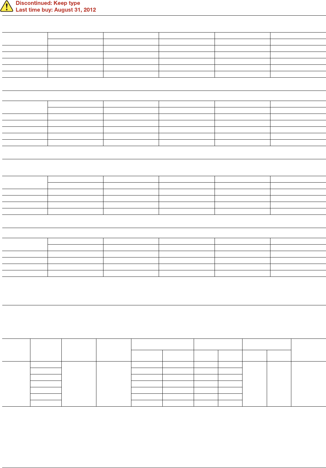
Type
Nominal coil
voltage
Pick-up voltage
(at 20°C 68°F)
Drop-out
voltage
(at 20°C 68°F)
Nominal coil current
[±20%] (at 20°C 68°F)
Coil inductance
Nominal operating
power
Max. applied
voltage
(at 70°C 158°F)
50Hz 60Hz
N.C.
condition
N.O.
condition
50Hz 60Hz
Standard
6V AC
80%V or less of
nominal voltage
(Initial)
30%V or more
of nominal
voltage
(Initial)
224mA 200mA 0.078H 0.074H
1.3VA 1.2VA
110%V of
nominal voltage
12V AC 111mA 100mA 0.312H 0.295H
24V AC 56mA 50mA 1.243H 1.181H
48V AC 28mA 25mA 4.974H 4.145H
100/110V AC 13.4/14.7mA 12/13.2mA 23.75H 20.63H
110/120V AC 12.2/13.5mA 10.9/11.9mA 27.19H 25.57H
200/220V AC 6.7/7.4mA 6/6.6mA 85.98H 81.76H
ASCTB4E 201201-T
Panasonic Corporation Automation Controls Business Unit industrial.panasonic.com/ac/e
HC
(2) DC coils
Notes: 1. The coil resistance for DC operation is the value measured when the coil temperature is 20°C 68°F. Compensate ±0.4% for every ±1°C change in temperature.
2. The relay operates in a range of 80% to 110% V of the voltage rating, but ideally, in consideration of temporary voltage fluctuations, it should be operated at the
rated voltage.
3. For use with 200 V DC, connect a 10 K (5W) resistor, in series, to the 100 V DC relay.
4. The maximum applied voltage is the maximum voltage fluctuation value for the coil power supply. This value is not a permissible value for continuous operation.
(This value differs depending on the ambient temperature. Please contact us for details.)
2) Specifications
Notes: *1. This value can change due to the switching frequency, environmental conditions and desired reliability level, therefore it is recommended to check this with the
actual load.
*2. For the AC coil types, the operate/release time will differ depending on the phase.
*3. The upper limit of the ambient temperature is the maximum temperature that can satisfy the coil temperature rise value. Refer to Usage, transport and storage
conditions in NOTES.
Type
Nominal coil
voltage
Pick-up voltage
(at 20°C 68°F)
Drop-out voltage
(at 20°C 68°F)
Nominal coil current
[±10%]
(at 20°C 68°F)
Coil resistance
[±10%]
(at 20°C 68°F)
Nominal operating
power
Max. applied voltage
(at 70°C 158°F)
Standard
6V DC
80%V or less of
nominal voltage
(Initial)
10%V or more of
nominal voltage
(Initial)
150mA 40
0.9W
110%V of
nominal voltage
12V DC 75mA 160
24V DC 37mA 650
48V DC 18.5mA 2,600
100/110V DC 10/11mA 10,000 1.0W
Characteristics Item Specifications
Contact
Arrangement 1 Form C 2 Form C 3 Form C 4 Form C 4 Form C (twin)
Contact resistance (Initial) Max. 30 m (By voltage drop 6 V DC 1A)
Contact material Ag alloy (cd free) + Au flash AgNi type + Au clad
Rating
Nominal switching capacity
(resistive load)
10A 250V AC 7A 250V AC 7A 250V AC 5A 250V AC 3A 250V AC
Max. switching power
(resistive load)
2,500VA 1,750VA 1,750VA 1,250VA 750VA
Max. switching voltage 250VAC
Max. switching current 10A 7A 7A 5A 3A
Nominal operating power AC (50Hz): 1.3VA, AC (60Hz): 1.2VA, DC: 0.9 to 1.1W
Min. switching capacity
(Reference value)*
1
1mA 1V DC 100µA 1V DC
Electrical
characteristics
Insulation resistance (Initial) Min. 1,000M (at 500V DC) Measurement at same location as “Breakdown voltage” section.
Breakdown
voltage
(Initial)
Between open
contacts
700 Vrms for 1min. (Detection current: 10mA.)
Between contact
sets
700 Vrms for 1min. (Detection current: 10mA.)
Between contact
and coil
2,000 Vrms for 1min. (Detection current: 10mA.)
Temperature rise (coil)
(at 70°C 158°F)
Max. 80°C 176°F (By resistive method, nominal coil voltage)
Operate time (at 20°C 68°F)*
2
Max. 20ms (Nominal coil voltage applied to the coil, excluding contact bounce time.)
Release time (at 20°C 68°F)*
2
Max. 20ms (Nominal coil voltage applied to the coil, excluding contact bounce time.) (without diode)
Mechanical
characteristics
Shock
resistance
Functional Min. 196 m/s
2
(Half-wave pulse of sine wave: 11 ms; detection time: 10µs.)
Destructive Min. 980 m/s
2
(Half-wave pulse of sine wave: 6 ms.)
Vibration
resistance
Functional 10 to 55 Hz at double amplitude of 1 mm (Detection time: 10µs.)
Destructive 10 to 55 Hz at double amplitude of 2 mm
Expected life
Mechanical Min. 5×10
7
: AC coil type (at 180 times/min.); Min. 10
8
: DC coil type (at 180 times/min.)
Electrical
Min. 2×10
5
resistive load
(at 20 times/min.)
Min. 2×10
5
resistive load
(at 20 times/min.)
Min. 10
5
resistive load
(at 20 times/min.)
Min. 2×10
5
resistive load
(at 20 times/min.)
Min. 2×10
5
resistive load
(at 20 times/min.)
Conditions
Conditions for operation,
transport and storage*
3
Ambient temperature: –50°C to +70°C –58°F to +158°F (without LED); –50°C to +60°C –58°F to +140°F (with LED)
Humidity: 5 to 85% R.H. (Not freezing and condensing at low temperature)
Max. Operating speed 20 times/min. (at max. rating)
Unit weight Approx. 30g 1.06 oz
ASCTB4E 201201-T
Panasonic Corporation Automation Controls Business Unit industrial.panasonic.com/ac/e
HC
3) Switching capacity and expected life
(1) Electrical (at 20 times/min.)
(2) Mechanical (at 180 times/min.)
AC coil type: Min. 5×10
7
; DC coil type: Min. 10
8
2. Amber sealed type
1) Coil data
Same coil data as HC relay standard type. Please refer to standard type information.
2) Specifications
Notes: Other specifications are same as standard types.
*1. This value can change due to the switching frequency, environmental conditions and desired reliability level, therefore it is recommended to check this with the
actual load.
*2. The upper limit of the ambient temperature is the maximum temperature that can satisfy the coil temperature rise value. Refer to Usage, transport and storage
conditions in NOTES.
3) Switching capacity and expected life
(1) Electrical (at 20 times/min.)
(2) Mechanical (at 180 times/min.)
AC coil type: Min. 5×10
7
; DC coil type: Min. 10
8
Load
AC DC
Expected lifeResistive (cos ϕ = 1) Inductive (cos ϕ 0.4) Resistive Inductive
Voltage 125V AC 250V AC 125V AC 250V AC 30V DC 30V DC
1 Form C
10A 10A 5A 3A Min. 2×10
5
7A 7A 3A 2.5A 3A 1A Min. 5×10
5
5A 5A 2A 1.5A Min. 10
6
2 Form C
7A 7A 3.5A 2A Min. 2×10
5
5A 5A 2.5A 1.5A 3A 0.6A Min. 5×10
5
3A 3A 1.5A 1A Min. 10
6
3 Form C
7A 7A ————Min. 10
5
——3.5A 2A Min. 2×10
5
5A 5A 3A 0.4A Min. 5×10
5
4 Form C
5A 5A 2A 1A Min. 2×10
5
3A 3A 1A 0.8A 3A 0.4A Min. 5×10
5
2A 2A 0.5A 0.4A Min. 10
6
4 Form C (twin) 3A 3A 1A 0.8A 3A Min. 2×10
5
Characteristics Item
Specifications
1 Form C 2 Form C 4 Form C 4 Form C (twin)
Contact Arrangement 1 Form C 2 Form C 4 Form C 4 Form C
Rating
Nominal switching capacity (resistive load) 5A 250V AC 3A 250V AC 2A 250V AC 1A 250V AC
Max. switching power (resistive load) 1,250VA 700VA 500VA 250VA
Max. switching voltage 250VAC 250VAC 250VAC 250VAC
Max. switching current 5A 3A 2A 1A
Min. switching capacity (Reference value)*
1
1mA 100mV DC 100µA 100mV DC
Electrical characteristics Temperature rise (coil) (at 60°C 140°F) Max. 90°C 194°F (By resistive method, nominal voltage)
Expected life Electrical Min. 2×10
5
resistive load (at 20 times/min.)
Conditions
Conditions for operation, transport and
storage*
2
Ambient temperature: –40°C to +60°C –40°F to +140°F;
Humidity: 5 to 85% R.H. (Not freezing and condensing at low temperature)
Ambient air pressure 760mmHg±20% (1,013mb±20%)
Load
AC DC
Expected lifeResistive (cos ϕ = 1) Inductive (cos ϕ 0.4) Resistive Inductive
Voltage 125V AC 250V AC 125V AC 250V AC 30V DC 30V DC
HC1E 5A 5A 3A 1A Min. 2×10
5
HC2E 3A 3A 2A 0.7A Min. 2×10
5
HC4E 2A 2A 2A 0.6A Min. 2×10
5
HC4ED (4 Form C twin) 1A 1A ————Min. 2×10
5
ASCTB4E 201201-T
Panasonic Corporation Automation Controls Business Unit industrial.panasonic.com/ac/e
PREVIOUS123456NEXT