Closed Dec 25th-26th
800-300-1968
We Stock Hard to Find Parts
My Account
|
My Orders
|
My Cart
Questions?
(800) 300-1968
Register
(current)
My Account
(current)
My Orders
(current)
My Cart
(current)
Categories
(current)
Manufacturers
Request a Quote
Sell Your Excess
Consignment
Quality Assurance
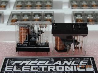
G2R-14-AC120
Part #
G2R-14-AC120
Description
RELAY GEN PURPOSE SPDT 10A 120V
Category
RELAY
Availability
In Stock
Qty
4
Qty
Price
1 +
$5.67639
Manufacturer
Available
Qty
OMRON CORP
Date Code: 0813
Freelance Stock:
4
Ships Immediately
Add to Cart
Related Items
OMRON
RELAY
G2R-1-E-ASIDC24
$7.31557
OMRON
RELAY
G2R-1-T
$21.76973
OMRON
RELAY
G2R-117P-V-RP-US-24VDC
$16.58646
OMRON
RELAY
G2R-14-24VDC
ARI
RELAY
0052A1H0B
Stego
RELAY
01142.0-00
$20.15425