SNAP Analog Input Modules
Opto 22 • 43044 Business Park Drive • Temecula, CA 92590-3614 • www.opto22.com
SALES 800-321-6786 • 951-695-3000 • FAX 951-695-3095 • sales@opto22.com • SUPPORT 800-835-6786 • 951-695-3080 • FAX 951-695-3017 • support@opto22.com
© 2001–2014 Opto 22. All rights reserved. Dimensions and specifications are subject to change. Brand or product names used herein are trademarks or registered trademarks of their respective companies or organizations.
SNAP Analog Input Modules
PAGE
14
DATA SHEET
Form 1065-140815
Thermistor Input Module 0–400 K, 0–200 K,
0–100 K, 0–50 K, 0–40 K, 0–20 K, 0–10 K,
0–5 K, 0–4 K, 0–2 K, 0–1 K, 0–500 Ohm
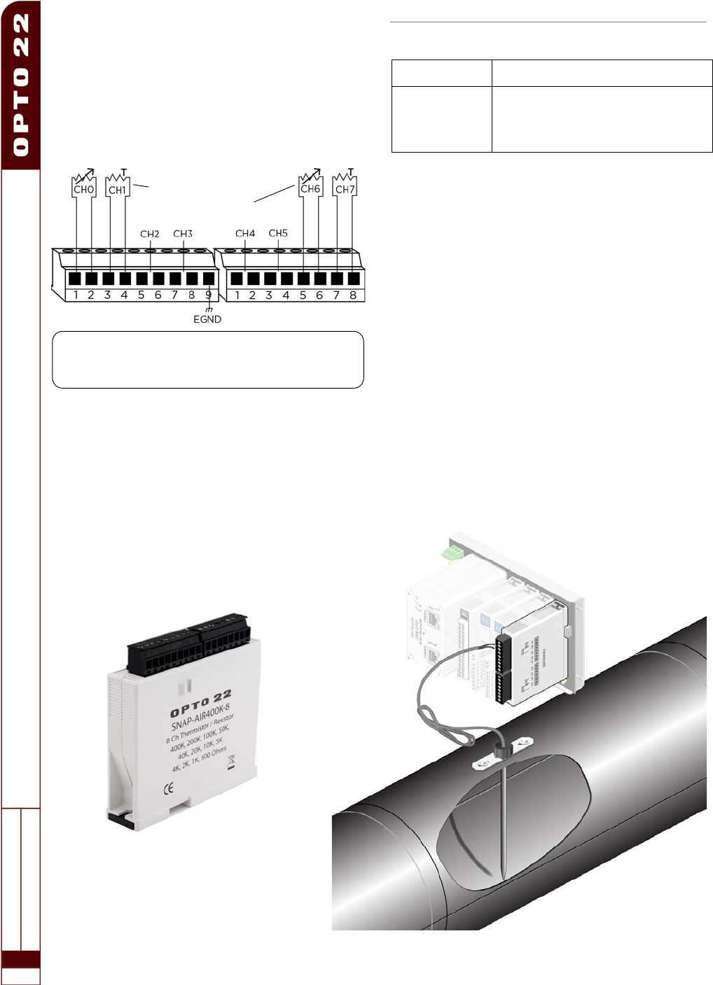
SNAP-AIR400K-8
IMPORTANT: The mounting rack connector has 24 pins; the module
connector has 20 pins. The extra pins on the mounting rack
connector prevent misalignment of the module during installation.
Description
The SNAP-AIR400K-8 module has eight channels of analog to
digital conversion that convert resistance to temperature or to
Ohms. The module is ideal for NTC thermisters commonly used
in HVAC, refrigeration, and process control applications. It may
also be used with PTC thermisters in resistance sensing
applications. See the table on
page 3
for I/O processor
compatibility.
NTC thermistor
Variable resistance device
Part Number Description
SNAP-AIR400K-8
Eight channel analog resistor/thermistor
input, 400 K Ohms, 200 K Ohms,
100 K Ohms, 50 K Ohms, 40 K Ohms,
20 K Ohms, 10 K Ohms, 5 K Ohms,
4 K Ohms, 2 K Ohms, 1 K Ohms, 500 Ohms
The SNAP-AIR400K-8 reads variable resistance type
transducers, and it has 12 resistance input ranges from 500
Ohms to 400 K Ohms, plus Autorange. Range dependent
resolution is from 20 milliOhms to 16 Ohms.
SNAP PAC brains and PAC Control provide direct temperature
readings for four popular thermistors using the Steinhart-Hart
equation (see page 16). You may also enter custom
coefficients for unsupported thermistor curves.
The simple two-wire connections are made to the pluggable
terminal strip on top of the module.
NOTE: The eight input channels must be electrically isolated from
each other and earth ground. The transducer resistor element
must be isolated from any electrically conducting probe tube
housing.
See page 15 for module specifications.
Wiring Information
Unshielded 24 AWG wire (minimum) is recommended.


