SNAP Analog Input Modules
Opto 22 • 43044 Business Park Drive • Temecula, CA 92590-3614 • www.opto22.com
SALES 800-321-6786 • 951-695-3000 • FAX 951-695-3095 • sales@opto22.com • SUPPORT 800-835-6786 • 951-695-3080 • FAX 951-695-3017 • support@opto22.com
© 2001–2014 Opto 22. All rights reserved. Dimensions and specifications are subject to change. Brand or product names used herein are trademarks or registered trademarks of their respective companies or organizations.
SNAP Analog Input Modules
DATA SHEET
Form 1065-140815
PAGE
9
Current Input Module, -20 mA to +20 mA, 32 Channels
Specifications
Description
The SNAP-AIMA-32 and SNAP-
AIMA-32-FM modules provide 32
channels of input with an input
range of
-20mA to +20mA. The SNAP-AIMA-
32-FM is Factory Mutual approved.
Check the table on page 3 for I/O
processor compatibility.
Dimensional drawings are on page 39.
These modules DO NOT supply loop excitation current.
Channels are not isolated from each other. Since all inputs
share a common reference, the module must be installed at
the beginning or end of a typical 4–20 mA loop. If you use
both standard and self-sourcing transmitters, put the
transmitters on different modules or use different power
supplies. (If you need channels that are isolated from each
other on the same module, see Opto 22 form #1182.)
Wiring
SNAP TEX cables and a breakout rack are available separately
for wiring points to field devices (see form #1756, the SNAP
TEX Cables & Breakout Boards Data Sheet). The SNAP-HD-BF6
cable connects the module to the breakout rack, which can
then be wired to field devices. (NOTE: The SNAP-HD-CBF6
wiring harness with flying leads is not recommended for this
module.)
CAUTION: We strongly recommend that you use the breakout
rack with these modules. Miswiring of any point on the
module can cause severe out-of-warranty damage. The
breakout rack protects the module from many wiring errors.
if you are using the module with loop power (2-wire) negative
common devices, connect to the SNAP-AIMA-HDB (or -FM)
rack. If you are using the module with self-powered devices
(4-wire) or with devices that share a common positive
connection, do not use the SNAP-AIMA-HDB (or -FM) boards,
which have a current limiting diode. Instead, wire to the SNAP-
AIV-HDB or SNAP-AIV-HDB-FM.
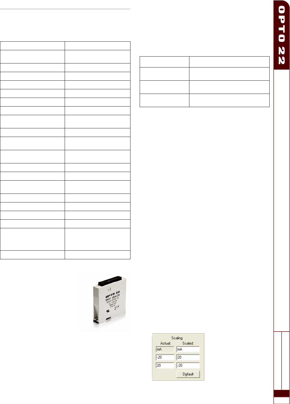
Correcting for Inverted Scaling
Positive readings for these modules appear as negative values.
Therefore, in order to obtain meaningful readings, use the
scaling feature in PAC Control as follows:
1. In the Add or Edit Analog Point dialog box for each point,
choose the scalable version of the module.
2. Under Scaling, scale each point negatively as shown
below:
Input Range -20 mA to +20 mA
Over-Range Limits
From -22 to +22 mA
(+/-20 mA range)
Resolution 0.8 microamps
Input Filtering -3 dB @ 31 Hz
Data Freshness (Max) 1.15 s
DC Common Mode Rejection >-120 dB
AC Common Mode Rejection >-120 dB @ 60 Hz
Maximum Survivable Input 36 mA or 9 VDC
Maximum Operating Common
Mode Voltage
250 V
Accuracy 0.1% (20 microamps)
DRIFT: Gain Temperature
Coefficient
30 PPM/ °C
DRIFT: Offset Temperature
Coefficient
15 PPM/ °C
Isolation 1500 V, field to logic
Power Requirements 5 VDC (±0.15 ) @ 150 mA
Input Resistance - Single
Ended
100 ohms (each channel)
Operating Temperature 0 °C to 70 °C
Storage Temperature -40 °C to 85 °C
Torque, hold-down screws 4 in-lb (0.45 N-m)
Torque, connector screws 5.26 in-lb (0.6 N-m)
Agency Approvals
SNAP-AIMA-32: UL, CE,
RoHS, DFARS.
SNAP-AIMA-32-FM: CE, FM,
RoHS, DFARS
Warranty Lifetime
Part Number Description
SNAP-AIMA-32
SNAP-AIMA-32-FM
32-channel analog current input,
-20mA to +20mA
SNAP-HD-BF6
Wiring harness for SNAP-AIMA-32
modules and breakout racks
SNAP-AIMA-HDB
SNAP-AIMA-HDB-FM
Breakout racks for SNAP-AIMA-32
and SNAP-AIMA-32-FM


