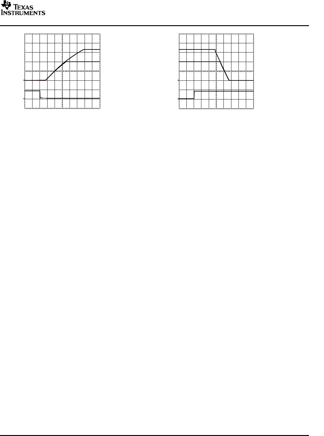
Freelance Electronics Components Distributor
Closed Dec 25th-26th
800-300-1968
We Stock Hard to Find Parts

PTV12020LAH

Part # PTV12020LAH
Description 12-V INPUT NON-ISOL WIDE-ADJUST SIP
Category MODULE
Availability In Stock
Qty 20
Qty Price
1 - 4 $24.36110
5 - 8 $19.37815
9 - 12 $18.27083
13 - 16 $16.97895
17 + $15.13341
Manufacturer Available Qty
Texas Instruments
  • Shipping Freelance Stock: 20
    Ships Immediately


Technical Document


DISCLAIMER: The information provided herein is solely for informational purposes. Customers must be aware of the suitability of this product for their application, and consider that variable factors such as Manufacturer, Product Category, Date Codes, Pictures and Descriptions may differ from available inventory.

www.ti.com
PTH12050W
Track
GND
PTV12020W
Track
GND
+
+
+
+
U1
U2
12 V
0 V
On/Off Control
1 = Power Down
0 = Power Up
Q1
BSS138
V
I
V
O
V
O
1 = 3.3 V
C
O
C
I
V
O
V
I
C1
0.1 F
C
O
R1
100 k
Sense
GND Adjust
R2
2 k
V
O
2 = 2 V
R3
8.06 k
C
I
Adjust
PTV12020W/L
SLTS231A NOVEMBER 2004 REVISED FEBRUARY 2005
The same circuit also provides a power-down sequence. Power down is the reverse of power up, and is
accomplished by lowering the track control voltage back to zero volts. The important constraint is that a valid
input voltage must be maintained until the power down is complete. It also requires that Q1 be turned off
relatively slowly. This is so that the Track control voltage does not fall faster than Auto-Track slew rate capability,
which is 1 V/ms. The components R1 and C1 in Figure 16 limit the rate at which Q1 pulls down the Track control
voltage. The values of 100 k and 0.1 µF correlate to a decay rate of about 0.17 V/ms.
The power-down sequence is initiated with a low-to-high transition at the On/Off Control input to the circuit.
Figure 18 shows the power-down waveforms. As the Track control voltage falls below the nominal set-point
voltage of each power module, then its output voltage decays with all the other modules under Auto-Track
control.
Notes on Use of Auto-Track™
1. The Track pin voltage must be allowed to rise above the module set-point voltage before the module can
regulate at its adjusted set-point voltage.
2. The Auto-Track function tracks almost any voltage ramp during power up, and is compatible with ramp
speeds of up to 1 V/ms.
3. The absloute maximum voltage that may be applied to the Track pin is the input voltage V
I
.
4. The module does not follow a voltage at its Track control input until it has completed its soft-start
initialization. This takes about 10 ms from the time that the module has sensed that a valid voltage has been
applied to its input. During this period, it is recommended that the Track pin be held at ground potential.
5. The module is capable of both sinking and sourcing current when following a voltage at its Track pin.
Therefore, start up into an output prebias cannot be supported when a module is under Auto-Track control.
Note: A prebias holdoff is not necessary when all supply voltages rise simultaneously under the control of
Auto-Track.
6. The Auto-Track function can be disabled by connecting the Track pin to the input voltage (V
I
). When
Auto-Track is disabled, the output voltage rises at a quicker and more linear rate after input power is applied.
Figure 16. Sequenced Power Up and Power Down Using Auto-Track
16
www.ti.com
Vo1 (1 V/Div)
Vo2 (1 V/Div)
On/Off Control
(5 V/Div)
HORIZ SCALE: 10 ms/Div
Vo1 (1 V/Div)
Vo2 (1 V/Div)
On/Off Control
(5 V/Div)
HORIZ SCALE: 10 ms/Div
Prebias Start-Up Capability
PTV12020W/L
SLTS231A NOVEMBER 2004 REVISED FEBRUARY 2005
Figure 17. Simultaneous Power Up With Auto-Track Figure 18. Simultaneous Power Down With Auto-Track
Control Control
A prebias start-up condition occurs as a result of an external voltage being present at the output of a power
module prior to its output becoming active. This often occurs in complex digital systems when current from
another power source is backfed through a dual-supply logic component, such as an FPGA or ASIC. Another
path might be via clamp diodes, sometimes used as part of a dual-supply power-up sequencing arrangement. A
prebias can cause problems with power modules that incorporate synchronous rectifiers. This is because under
most operating conditions, such modules can sink as well as source output current. The 12-V input modules
incorporate synchronous rectifiers, but do not sink current during start up, or whenever the Inhibit pin is held low.
Start up includes an initial delay (approximately 8–15 ms), followed by the rise of the output voltage under the
control of the module internal soft-start mechanism; see Figure 19 .
Conditions for Prebias Holdoff
In order for the module to allow an output prebias voltage to exist (and not sink current), certain conditions must
be maintained. The module holds off a prebias voltage when the Inhibit pin is held low, and whenever the output
is allowed to rise under soft-start control. Power up under soft-start control occurs on the removal of the ground
signal to the Inhibit pin (with input voltage applied), or when input power is applied with Auto-Track disabled
2
. To
further ensure that the regulator does not sink output current (even with a ground signal applied to its Inhibit), the
input voltage must always be greater than the applied prebias source. This condition must exist throughout the
power-up sequence
3
.
The soft-start period is complete when the output begins rising above the prebias voltage. Once it is complete,
the module functions as normal and sinks current if a voltage higher than the nominal regulation value is applied
to its output.
Note: If a prebias condition is not present, the soft-start period is complete when the output voltage has risen to
either the set-point voltage, or the voltage applied at the module Track control pin, whichever is lowest, to its
output.
Demonstration Circuit
Figure 20 shows the start-up waveforms for the demonstration circuit shown in Figure 21 . The initial rise in V
O
2 is
the prebias voltage, which is passed from the VCCIO to the VCORE voltage rail through the ASIC. Note that the
output current from the module (I
O
2) is negligible until its output voltage rises above the applied prebias.
17
www.ti.com
Vo (1 V/Div)
1
Vo (1 V/Div)
2
Io (5 A/Div)
2
HORIZ SCALE: 10 ms/Div
Vin (5 V/Div)
Vo (1 V/Div)
HORIZ SCALE 5 ms/Div
Start−Up
Period
ASIC
VCORE
VCCIO
PTV12010W
6
Track
GNDInhibit Vadj
Sense
+
+
+
PTV12020W
Track
GNDInhibit Adjust
C3
+
TL7702B
GND
SENSE
REF
CT
RESET
0.68 F
C4
+
0.1 F
Sense
V
O
V
I
V
O
V
I
RESIN
11 k
100 k
10 k
C1
C2
R3
R4
C5
C6
R5
RESET
V
CC
V
I
= 12 V V
O
1 = 3.3 V
V
O
2 = 1.8 V
I
O
2
R1
2 k
R2
11.5 k
5
8
7
2
1
3
4
PTV12020W/L
SLTS231A NOVEMBER 2004 REVISED FEBRUARY 2005
Figure 19. PTV12020W Start Up Figure 20. Prebias Start-Up Waveforms
NOTES:
1. The prebias start-up feature is not compatible with Auto-Track. If the rise in the output is limited by the
voltage applied to the Track control pin, the output sinks current during the period that the track control
voltage is below that of the back-feeding source. For this reason, Auto-Track should be disabled when not
being used. This is accomplished by connecting the Track pin to the input voltage, V
I
. This raises the Track
pin well above the set-point voltage prior to start up, thereby defeating the Auto-Track feature.
2. To further ensure that the regulator output does not sink current when power is first applied (even with a
ground signal applied to the Inhibit control pin), the input voltage must always be greater than the applied
prebias source. This condition must exist throughout the power-up sequence of the power system.
Figure 21. Application Circuit Demonstrating Prebias Startup
18
PREVIOUS12345678NEXT