Closed Dec 25th-26th
800-300-1968
We Stock Hard to Find Parts
My Account
|
My Orders
|
My Cart
Questions?
(800) 300-1968
Register
(current)
My Account
(current)
My Orders
(current)
My Cart
(current)
Categories
(current)
Manufacturers
Request a Quote
Sell Your Excess
Consignment
Quality Assurance
4A001
Part #
4A001
Description
Limit Switch, Operating Head
Category
LED
Availability
In Stock
Qty
3
Qty
Price
1 - 2
$16.12311
3 +
$12.21448
Manufacturer
Available
Qty
PEERLESS ELECTRONICS
Freelance Stock:
3
Ships Immediately
Add to Cart
Related Items
SCHURTER
LED
0035.0727
$10.81417
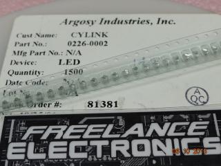
ARGOSY INDUSRTIES INC.
LED
0226-0002
$0.27485
LEDTRONICS
LED
0286A5442P0A43
LEDTRONICS
LED
0286A5442P0A52
LEDTRONICS
LED
0286A5442P0A53
LEDTRONICS
LED
0286A5442P0A92