3–6
3.4.6 I
2
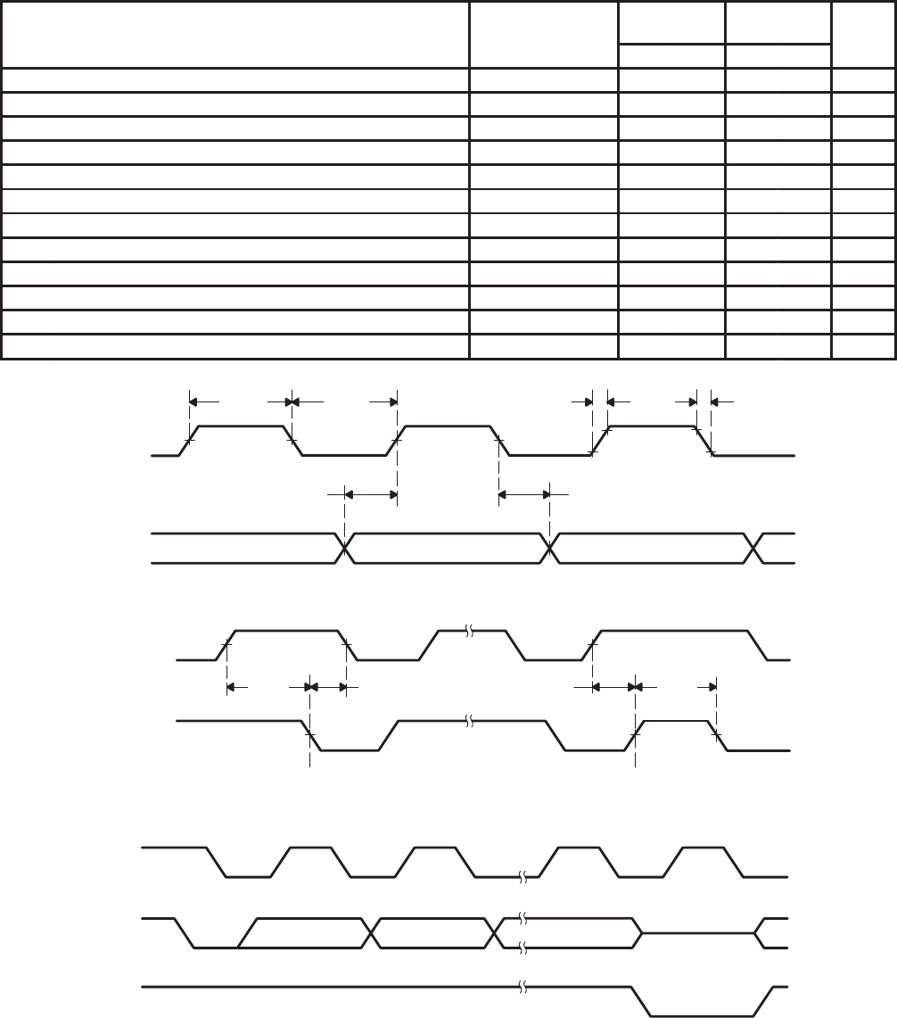
C Interface Signals Over Recommended Operating Conditions
(unless otherwise noted)
PARAMETER TEST CONDITIONS
STANDARD
MODE
FAST MODE
UNITS
MIN MAX MIN MAX
f
SCL
Frequency, SCL 0 100 0 400 kHz
t
w(H)
Pulse duration, SCL high 4 0.6 µs
t
w(L)
Pulse duration, SCL low 4.7 1.3 µs
t
r
Rise time, SCL and SDA 1000 300 ns
t
f
Fall time, SCL and SDA 300 300 ns
t
su1
Setup time, SDA to SCL 250 100 ns
t
h1
Hold time, SCL to SDA 0 0 ns
t
buf
Bus free time between stop and start condition 4.7 1.3 µs
t
su2
Setup time, SCL to start condition 4.7 0.6 µs
t
h2
Hold time, start condition to SCL 4 0.6 µs
t
su3
Setup time, SCL to stop condition 4 0.6 µs
C
L
Load capacitance for each bus line 400 400 pF
t
w(H)
t
w(L)
t
r
t
f
t
su1
t
h1
SCL
SDA
Figure 3–7. SCL and SDA Timing Waveforms
t
su2
t
h2
t
su3
t
buf
SCL
SDA
Start Condition Stop Condition
Figure 3–8. Start and Stop Conditions Timing Waveforms
12 89SCL
SDA OUT
SDA IN
Figure 3–9. Acknowledge Timing Waveform


