Introduction
25
November 2002 − Revised January 2005 SPRS205D
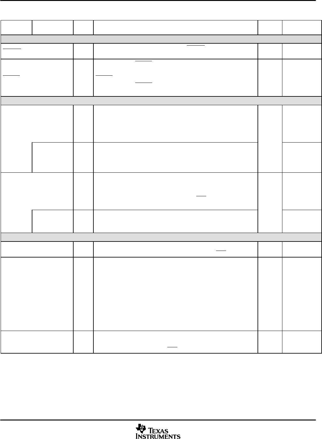
Table 2−3. Signal Descriptions (Continued)
TERMINAL
NAME
RESET
CONDITION
BK
‡
FUNCTIONI/O/Z
†
MULTIPLEXED
SIGNAL NAME
INTERRUPT AND RESET PINS
INT[4:0] I
Active-low external user interrupt inputs. INT[4:0] are maskable and are
prioritized by the interrupt enable register (IER) and the interrupt mode bit.
H, FS Input
RESET I
Active-low reset. RESET causes the digital signal processor (DSP) to
terminate execution and forces the program counter to FF8000h. When
RESET is brought to a high level, execution begins at location FF8000h of
program memory. RESET affects various registers and status bits. Use an
external pullup resistor on this pin.
H, FS Input
BIT I/O SIGNALS
GPIO[7:6,4:0] (LQFP)
GPIO[7:0] (BGA)
I/O/Z
7-bit (LQFP package) or 8-bit (BGA package) Input/Output lines that can
be individually configured as inputs or outputs, and also individually set or
reset when configured as outputs. At reset, these pins are configured as
inputs. After reset, the on-chip bootloader samples GPIO[3:0] to
determine the boot mode selected.
BK
(GPIO5
only)
Input
EMIF.CKE
(GPIO4)
O/Z
SDRAM CKE signal. The GPIO4 pin can be configured to serve as
SDRAM CKE pin by setting the following bits in the External Bus Selection
Register: CKE SEL = 1 and CKE EN = 1. In default mode, this pin serves as
GPIO4.
(except
GPIO5)
Input
(GPIO4)
XF O/Z
External flag. XF is set high by the BSET XF instruction, set low by BCLR
XF instruction or by loading ST1. XF is used for signaling other processors
in multiprocessor configurations or used as a general-purpose output pin.
XF goes into the high-impedance state when OFF is low, and is set high
following reset.
Output
EMIF.CKE O/Z
SDRAM CKE signal. The XF pin can be configured to serve as SDRAM
CKE pin by setting the following bits in the External Bus Selection Register:
CKE SEL = 0 and CKE EN = 1. In default mode, this pin serves as XF.
Output
(XF)
OSCILLATOR/CLOCK SIGNALS
CLKOUT O/Z
DSP clock output signal. CLKOUT cycles at the machine-cycle rate of the
CPU. CLKOUT goes into high-impedance state when OFF is low.
Output
X2/CLKIN I/O
System clock/oscillator input. If the internal oscillator is not being used,
X2/CLKIN functions as the clock input.
NOTE: The USB module requires a 48 MHz clock. Since this input clock
is used by both the CPU PLL and the USB module PLL, it must
be a factor of 48 MHz in order for the programmable PLL to
produce the required 48 MHz USB module clock.
In CLKGEN domain idle (OSC IDLE) mode, this pin becomes
output and is driven low to stop external crystals (if used) from
oscillating or an external clock source from driving the DSP’s
internal logic.
Oscillator
Input
X1 O
Output pin from the internal system oscillator for the crystal. If the internal
oscillator is not used, X1 should be left unconnected. X1 does not go into
the high-impedance state when OFF is low.
Oscillator
Output
†
I = Input, O = Output, S = Supply, Hi-Z = High-impedance
‡
BK = bus keeper (the bus keeper maintains the previous voltage level during reset or while the output pin is not driven), PU = pullup,
PD = pulldown, H = hysteresis input buffer, FS = fail-safe buffer


