Introduction
20
November 2002 − Revised January 2005SPRS205D
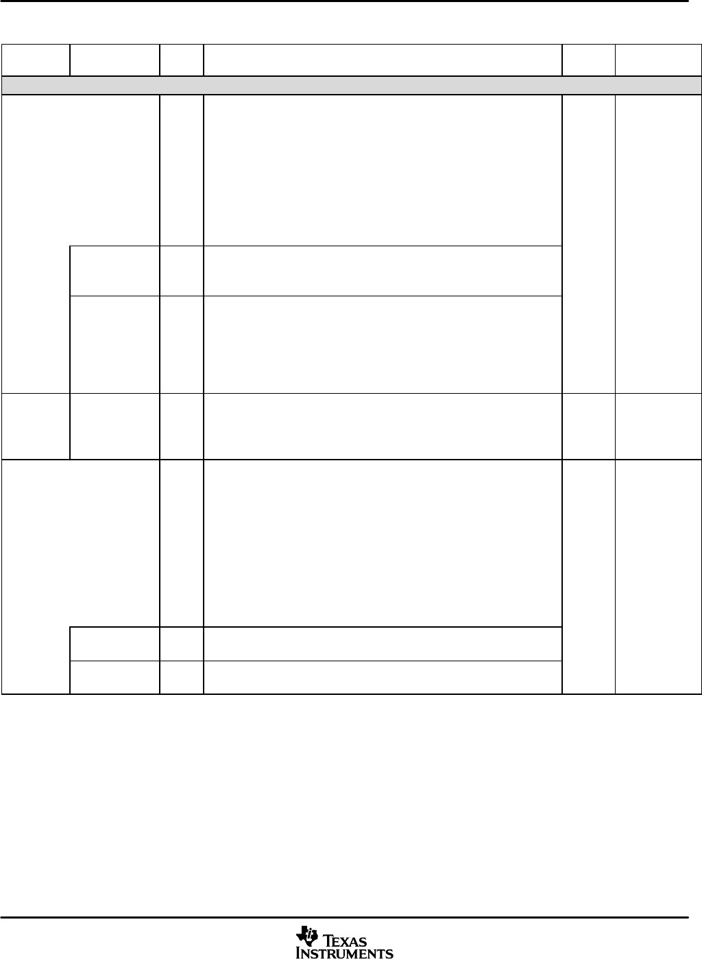
Table 2−3. Signal Descriptions (Continued)
TERMINAL
NAME
RESET
CONDITION
BK
‡
FUNCTIONI/O/Z
†
MULTIPLEXED
SIGNAL NAME
PARALLEL BUS (CONTINUED)
A[15:14]
(BGA only)
I/O/Z
A subset of the parallel address bus A15−A14 of the C55x DSP core
bonded to external pins. These pins serve in one of two functions: EMIF
address bus (EMIF.A[15:14]), or general-purpose I/O (GPIO.A[15:14]).
The initial state of these pins depends on the GPIO0 pin. See Section 3.5.1
for more information.
The address bus has a bus holder feature that eliminates passive
component requirement and the power dissipation associated with them.
The bus holders keep the address bus at the previous logic level when the
bus goes into a high-impedance state.
GPIO0 = 1:
Output,
EMIF.A[15:14]
EMIF.A[15:14] O/Z
EMIF address bus. EMIF.A[15:14] is selected when the Parallel Port Mode
bit field of the External Bus Selection Register is 01. This setting enables
the full EMIF mode and the EMIF drives the parallel port address bus.
GPIO0 = 0:
Input,
GPIO.A[15:14] I/O/Z
General-purpose I/O address bus. GPIO.A[15:14] is selected when the
Parallel Port Mode bit field of the External Bus Selection Register is 11.
This setting enables the HPI in multiplexed mode with the Parallel Port
GPIO register controlling the parallel port address bus. GPIO is also
selected when the Parallel Port Mode bit field is 00, enabling the Data
EMIF mode.
A[20:16]
(BGA only)
EMIF.A[20:16] O/Z
EMIF address bus. At reset, these address pins are set as output.
NOTE: These pins only function as EMIF address pins and they are not
multiplexed for any other function.
Output
D[15:0] I/O/Z
A subset of the parallel bidirectional data bus D31−D0 of the C55x DSP
core. These pins serve in one of two functions: EMIF data bus
(EMIF.D[15:0]) or HPI data bus (HPI.HD[15:0]). The initial state of these
pins depends on the GPIO0 pin. See Section 3.5.1 for more information.
The data bus includes bus keepers to reduce the static power dissipation
caused by floating, unused pins. This eliminates the need for external bias
resistors on unused pins. When the data bus is not being driven by the
CPU, the bus keepers keep the pins at the logic level that was most
recently driven. (The data bus keepers are disabled at reset, and can be
enabled/disabled under software control.)
BK
GPIO0 = 1:
Input,
EMIF.D[15:0]
GPIO0 = 0:
Input,
EMIF.D[15:0] I/O/Z
EMIF data bus. EMIF.D[15:0] is selected when the Parallel Port Mode bit
field of the External Bus Selection Register is 00 or 01.
HPI.HD[15:0] I/O/Z
HPI data bus. HPI.HD[15:0] is selected when the Parallel Port Mode bit
field of the External Bus Selection Register is 10 or 11.
†
I = Input, O = Output, S = Supply, Hi-Z = High-impedance
‡
BK = bus keeper (the bus keeper maintains the previous voltage level during reset or while the output pin is not driven), PU = pullup,
PD = pulldown, H = hysteresis input buffer, FS = fail-safe buffer


