Functional Overview
67
November 2002 − Revised January 2005 SPRS205D
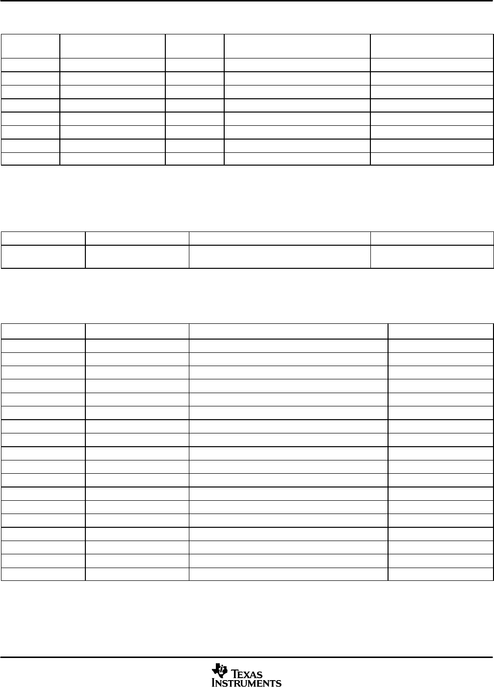
Table 3−31. GPIO
WORD
ADDRESS
REGISTER
NAME
PIN DESCRIPTION
RESET VALUE
†
0x3400 IODIR[7:0] GPIO[7:0] General-purpose I/O Direction Register 0000 0000 0000 0000
0x3401 IODATA[7:0] GPIO[7:0] General-purpose I/O Data Register 0000 0000 xxxx xxxx
0x4400 AGPIOEN[15:0] A[15:0] Address/GPIO Enable Register 0000 0000 0000 0000
0x4401 AGPIODIR[15:0] A[15:0] Address/GPIO Direction Register 0000 0000 0000 0000
0x4402 AGPIODATA[15:0] A[15:0] Address/GPIO Data Register xxxx xxxx xxxx xxxx
0x4403 EHPIGPIOEN[5:0] GPIO[13:8] EHPI/GPIO Enable Register 0000 0000 0000 0000
0x4404 EHPIGPIODIR[5:0] GPIO[13:8] EHPI/GPIO Direction Register 0000 0000 0000 0000
0x4405 EHPIGPIODATA[5:0] GPIO[13:8] EHPI/GPIO Data Register 0000 0000 00xx xxxx
†
Hardware reset; x denotes a “don’t care.”
Table 3−32. Device Revision ID
WORD ADDRESS REGISTER NAME DESCRIPTION VALUE
‡
0x3803 Rev ID[4:1] Silicon Revision Identification
Rev. 1.0: xxxx xxxx xxx0 000x
Rev. 1.1: xxxx xxxx xxx0 001x
‡
x denotes a “don’t care.”
Table 3−33. I
2
C Module Registers
WORD ADDRESS REGISTER NAME DESCRIPTION
RESET VALUE
†
0x3C00 I2COAR[9:0]
§
I
2
C Own Address Register 0000 0000 0000 0000
0x3C01 I2CIMR I
2
C Interrupt Mask Register 0000 0000 0000 0000
0x3C02 I2CSTR I
2
C Status Register 0000 0001 0000 0000
0x3C03 I2CCLKL[15:0] I
2
C Clock Divider Low Register 0000 0000 0000 0000
0x3C04 I2CCLKH[15:0] I
2
C Clock Divider High Register 0000 0000 0000 0000
0x3C05 I2CCNT[15:0] I
2
C Data Count 0000 0000 0000 0000
0x3C06 I2CDRR[7:0] I
2
C Data Receive Register 0000 0000 0000 0000
0x3C07 I2CSAR[9:0] I
2
C Slave Address Register 0000 0011 1111 1111
0x3C08 I2CDXR[7:0] I
2
C Data Transmit Register 0000 0000 0000 0000
0x3C09 I2CMDR[14:0] I
2
C Mode Register 0000 0000 0000 0000
0x3C0A I2CIVR I
2
C Interrupt Vector Register 0000 0000 0000 0000
0x3C0B − Reserved
0x3C0C I2CPSC I
2
C Prescaler Register 0000 0000 0000 0000
0x3C0D − Reserved
0x3C0E − Reserved
0x3C0F I2CMDR2 I
2
C Mode Register 2 0000 0000 0000 0000
− I2CRSR I
2
C Receive Shift Register (not accessible to the CPU)
− I2CXSR I
2
C Transmit Shift Register (not accessible to the CPU)
†
Hardware reset; x denotes a “don’t care.”
§
Specifies a unique 5509A I
2
C address. This register must be set by the programmer. When this device is used in conjunction with another I
2
C
master device, the register must be programmed to the I
2
C slave address (01011xx) allocated by Philips Semiconductor for the 5509A. The
two LSBs are programmable address bits.
NOTE: I
2
C protocol compatible, no fail-safe buffer.


