Freelance Electronics Components Distributor
Closed Dec 25th-26th
800-300-1968
We Stock Hard to Find Parts

TLC556MJB

Part # TLC556MJB
Description Standard Timer Dual 14-Pin CDIP Tube - Rail/Tube
Category IC
Availability Out of Stock
Qty 0
Qty Price
1 + $4.00000


Technical Document


DISCLAIMER: The information provided herein is solely for informational purposes. Customers must be aware of the suitability of this product for their application, and consider that variable factors such as Manufacturer, Product Category, Date Codes, Pictures and Descriptions may differ from available inventory.

TLC556, TLC556Y
DUAL LinCMOS TIMERS
SLFS047B – FEBRUARY 1984 – REVISED SEPTEMBER 1997
10
POST OFFICE BOX 655303 DALLAS, TEXAS 75265
APPLICATION INFORMATION
0.1 µF
0.1 µF
C
T
C
L
R
L
Output
R
B
R
A
GND
TRIG
THRES
RESET
DISCH
CONT V
DD
OUT
V
DD
2/3 V
DD
1/3 V
DD
GND
t
PHL
t
PLH
t
H
t
L
CIRCUIT TRIGGER
AND
THRESHOLD
VOLTAGE
WAVEFORM
TLC556
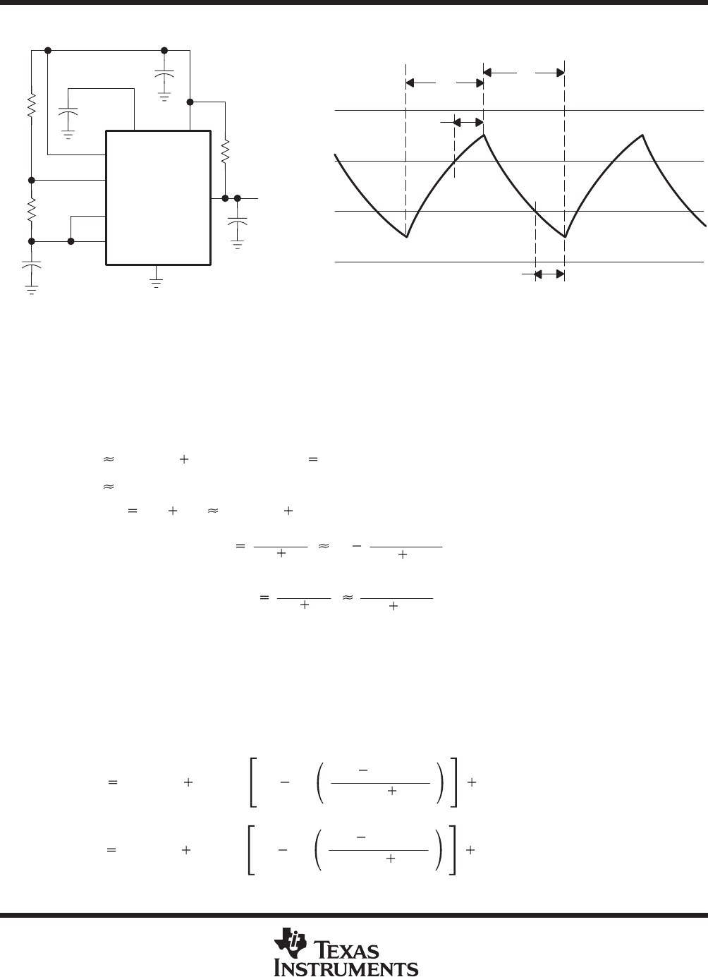
Figure 3. Astable Operation
Connecting the trigger input to the threshold input, as shown in Figure 3, causes the timer to run as a
multivibrator. The capacitor C
T
charges through R
A
and R
B
to the threshold voltage level (approximately 0.67
V
DD
) and then discharges through R
B
only to the value of the trigger voltage level (approximately 0.33 V
DD
).
The output is high during the charging cycle (t
H
) and low during the discharge cycle (t
L
). The duty cycle is
controlled by the values of R
A
, and R
B
, and C
T
, as shown in the equations below.
t
H
C
T
(R
A
R
B
) In 2 (In 2 0.693)
t
L
C
T
R
B
In 2
Period t
H
t
L
C
T
(R
A
2R
B
)In2
Output driver duty cycle
t
L
t
H
t
L
1
R
B
R
A
2R
B
Output waveform duty cycle
t
H
t
H
t
L
R
B
R
A
2R
B
The 0.1-µF capacitor at CONT in Figure 3 decreases the period by about 10%.
The formulas shown above do not allow for any propagation delay from the trigger and threshold inputs to the
discharge output. These delay times add directly to the period and create differences between calculated and
actual values that increase with frequency. In addition, the discharge output resistance r
on
adds to R
B
to provide
another source of error in the calculation when R
B
is very low or r
on
is very high.
The equations below provide better agreement with measured values.
t
H
C
T
(R
A
R
B
)In 3 exp
t
PLH
C
T
(R
B
r
on
)
t
PHL
t
L
C
T
(R
B
r
on
)In 3 exp
t
PHL
C
T
(R
A
R
B
)
t
PLH
TLC556, TLC556Y
DUAL LinCMOS TIMERS
SLFS047B – FEBRUARY 1984 – REVISED SEPTEMBER 1997
11
POST OFFICE BOX 655303 DALLAS, TEXAS 75265
APPLICATION INFORMATION
The preceding equations and those given earlier are similar in that a time constant is multiplied by the logarithm
of a number or function. The limit values of the logarithmic terms must be between In 2 at low frequencies and
In 3 at extremely high frequencies. For a duty cycle close to 50%, an appropriate constant for the logarithmic
terms can be substituted with good results. Duty cycles less than 50%
t
H
t
H
t
L
will require that
t
H
t
L
<1 and
possibly R
A
r
on
. These conditions can be difficult to obtain.
In monostable applications, the trip point of the trigger input can be set by a voltage applied to CONT. An input
voltage between 10% and 80% of the supply voltage from a resistor divider with at least 500-µA bias provides
good results.
TLC556, TLC556Y
DUAL LinCMOS TIMERS
SLFS047B – FEBRUARY 1984 – REVISED SEPTEMBER 1997
12
POST OFFICE BOX 655303 DALLAS, TEXAS 75265
MECHANICAL INFORMATION
D (R-PDSO-G**) PLASTIC SMALL-OUTLINE PACKAGE
14 PIN SHOWN
4040047/D 10/96
0.228 (5,80)
0.244 (6,20)
0.069 (1,75) MAX
0.010 (0,25)
0.004 (0,10)
1
14
0.014 (0,35)
0.020 (0,51)
A
0.157 (4,00)
0.150 (3,81)
7
8
0.044 (1,12)
0.016 (0,40)
Seating Plane
0.010 (0,25)
PINS **
0.008 (0,20) NOM
A MIN
A MAX
DIM
Gage Plane
0.189
(4,80)
(5,00)
0.197
8
(8,55)
(8,75)
0.337
14
0.344
(9,80)
16
0.394
(10,00)
0.386
0.004 (0,10)
M
0.010 (0,25)
0.050 (1,27)
0°–8°
NOTES: A. All linear dimensions are in inches (millimeters).
B. This drawing is subject to change without notice.
C. Body dimensions do not include mold flash or protrusion, not to exceed 0.006 (0,15).
D. Falls within JEDEC MS-012
PREVIOUS123456NEXT