5I
2
CSerial-ControlInterface(SlaveAddresses0x36and0x37)
5.1GeneralI
2
COperation
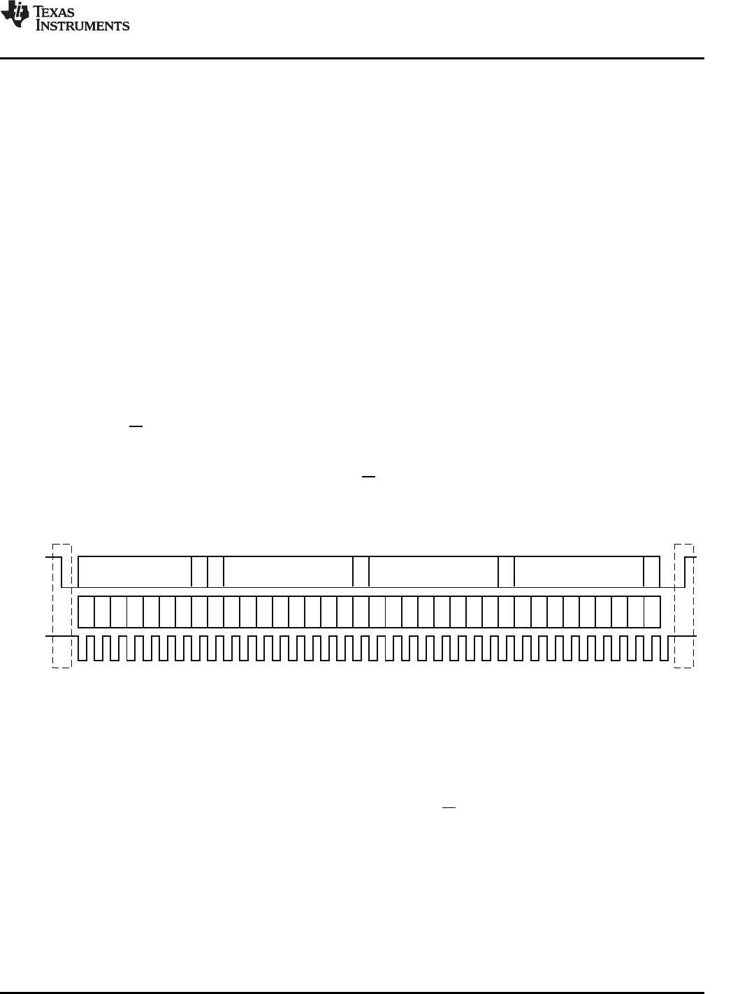
7-BitSlave Address
R/
W
8-BitRegister Address(N)
A
8-BitRegisterDataFor
Address(N)
Start Stop
SDA
SCL
7
6
5
4
3
2 1
0
7
6
5
4
3
2 1
0
7
6
5
4
3
2 1
0
7
6
5
4
3
2 1
0
A
8-BitRegisterDataFor
Address(N)
A A
T0035-01
TAS5518C
8-ChannelDigitalAudioPWMProcessor
www.ti.com
SLES238A–SEPTEMBER2008–REVISEDJULY2009
TheTAS5518ChasabidirectionalI
2
CinterfacethatiscompatiblewiththeInter-IC(I
2
C)busprotocoland
supportsboth100-kbpsand400-kbpsdatatransferratesforsingle-andmultiple-bytewriteandread
operations.Thisisaslave-onlydevicethatdoesnotsupportamultimasterbusenvironmentorwaitstate
insertion.Thecontrolinterfaceisusedtoprogramtheregistersofthedeviceandtoreaddevicestatus.
TheTAS5518Csupportsthestandard-modeI
2
Cbusoperation(100kHzmaximum)andthefastI
2
Cbus
operation(400kHzmaximum).TheTAS5518CperformsallI
2
CoperationswithoutI
2
Cwaitcycles.
TheI
2
Cwriteaddressis0x36andtheI
2
Creadaddressis0x37.
TheI
2
Cbusemploystwosignals—SDA(data)andSCL(clock)—tocommunicatebetweenintegrated
circuitsinasystem.Dataistransferredonthebusserially,onebitatatime.Theaddressanddatacanbe
transferredinbyte(8-bit)format,withthemostsignificantbit(MSB)transferredfirst.Inaddition,eachbyte
transferredonthebusisacknowledgedbythereceivingdevicewithanacknowledgebit.Eachtransfer
operationbeginswiththemasterdevicedrivingastartconditiononthebusandendswiththemaster
devicedrivingastopconditiononthebus.ThebususestransitionsonSDAwhiletheclockishighto
indicatestartandstopconditions.Ahigh-to-lowtransitiononSDAindicatesastartandalow-to-high
transitionindicatesastop.Normaldatabittransitionsmustoccurwithinthelowtimeoftheclockperiod.
TheseconditionsareshowninFigure5-1.Themastergeneratesthe7-bitslaveaddressandthe
read/write(R/W)bittoopencommunicationwithanotherdeviceandthenwaitsforanacknowledge
condition.TheTAS5518CholdsSDAlowduringtheacknowledgeclockperiodtoindicatean
acknowledgement.Whenthisoccurs,themastertransmitsthenextbyteofthesequence.Eachdeviceis
addressedbyaunique7-bitslaveaddressplusR/Wbit(1byte).Allcompatibledevicessharethesame
signalsviaabidirectionalbususingawired-ANDconnection.Anexternalpullupresistormustbeusedfor
theSDAandSCLsignalstosetthehighlevelforthebus.
Figure5-1.TypicalI
2
CSequence
Thenumberofbytesthatcanbetransmittedbetweenstartandstopconditionsisunlimited.Whenthelast
wordtransfers,themastergeneratesastopconditiontoreleasethebus.Agenericdatatransfer
sequenceisshowninFigure5-1.
The7-bitaddressfortheTAS5518Cis0011011.WhentheR/WbitisaddedastheLSB,theI
2
Cwrite
addressis0x36andtheI
2
Creadaddressis0x37.
SubmitDocumentationFeedback63
I
2
CSerial-ControlInterface(SlaveAddresses0x36and0x37)
Not Recommended For New Designs


