4.6.3I
2
CSerialControlPortOperation
TAS5518C
8-ChannelDigitalAudioPWMProcessor
www.ti.com
SLES238A–SEPTEMBER2008–REVISEDJULY2009
TimingCharacteristicsforI
2
CInterfaceSignalsoverrecommendedoperatingconditions(unlessotherwisenoted)
STANDARDMODEFASTMODE
PARAMETERTESTCONDITIONSUNIT
MINMAXMINMAX
f
SCL
SCLclockfrequency01000400kHz
Holdtime(repeated)START
t
HD-STA
condition.Afterthisperiod,thefirst40.6µs
clockpulseisgenerated.
t
LOW
LOWperiodoftheSCLclock4.71.3µs
t
HIGH
HIGHperiodoftheSCLclock40.6µs
t
SU-STA
SetuptimeforrepeatedSTART4.70.6µs
t
SU-DAT
Datasetuptime250100µs
t
HD-DAT
Dataholdtime
(1)(2)
03.4500.9µs
20+0.1
t
r
RisetimeofbothSDAandSCL1000500
(4)
ns
C
b
(3)
20+0.1
t
f
FalltimeofbothSDAandSCL300300ns
C
b
(3)
t
SU-STO
SetuptimeforSTOPcondition40.6µs
BusfreetimebetweenaSTOPand
t
BUF
4.71.3µs
STARTcondition
C
b
Capacitiveloadsforeachbusline400400pF
NoisemarginattheLOWlevelfor
VnLeachconnecteddevice(including0.1×V
DD
0.1×V
DD
V
hysteresis)
NoisemarginattheHIGHlevelfor
V
nH
eachconnecteddevice(including0.2×V
DD
0.2×V
DD
V
hysteresis)
(1)NotethatSDAdoesnothavethestandardI
2
Cspecification300-nsholdtimeandthatSDAmustbevalidbytherisingandfallingedges
ofSCL.TIrecommendsthata3.3-kWpullupresistorbeusedtoavoidpotentialtimingissues.
(2)Afast-modeI
2
C-busdevicecanbeusedinastandard-modeI
2
C-bussystem,buttherequirementt
SU-DAT
≥250nsmustthenbemet.
ThisisautomaticallythecaseifthedevicedoesnotstretchtheLOWperiodoftheSCLsignal.IfsuchadevicedoesstretchtheLOW
periodoftheSCLsignal,itmustoutputthenextdatabittotheSDAlinet
r-max
+t
SU-DAT
=1000+250=1250ns(accordingtothe
standard-modeI
2
Cbusspecification)beforetheSCLlineisreleased.
(3)C
b
=totalcapacitanceofonebuslineinpF.
(4)Risetimevarieswithpullupresistor.
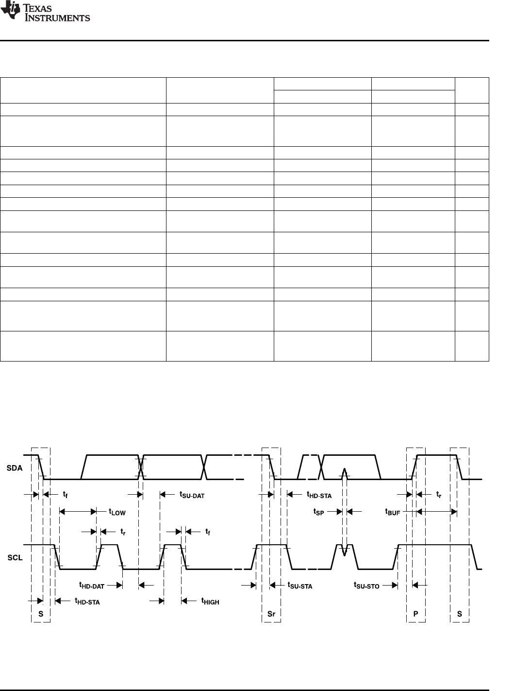
Figure4-2.SCLandSDATiming
SubmitDocumentationFeedbackElectricalSpecifications55
Not Recommended For New Designs


