Freelance Electronics Components Distributor
Closed Dec 25th-26th
800-300-1968
We Stock Hard to Find Parts

TAS5518CPAG

Part # TAS5518CPAG
Description 8 CHANNEL DIGITAL AUDIO PWM PROCESSOR
Category IC
Availability In Stock
Qty 2
Qty Price
1 + $13.60858
Manufacturer Available Qty
Texas Instruments
  • Shipping Freelance Stock: 2
    Ships Immediately


Technical Document


DISCLAIMER: The information provided herein is solely for informational purposes. Customers must be aware of the suitability of this product for their application, and consider that variable factors such as Manufacturer, Product Category, Date Codes, Pictures and Descriptions may differ from available inventory.

B0017-01
Loudness
Biquad
H(z)
Audio OutAudio In
V
VLoudness Function = f(V)
2.9.1LoudnessExample
TAS5518C
8-ChannelDigitalAudioPWMProcessor
www.ti.com
SLES238ASEPTEMBER2008REVISEDJULY2009
TAS5518Cloudnessimplementationtracksthevolumecontrolsettingtoprovidespectralcompensation
forweaklow-orhigh-frequencyresponseatlowvolumelevels.Forthevolumetrackingfunction,both
linearandlogarithmiccontrollawscanbeimplemented.Anybiquadfilterresponsecanbeusedtoprovide
thedesiredloudnesscurve.ThecontrolparametersfortheloudnesscontrolareprogrammableviatheI
2
C
interface.
TheTAS5518Chasasinglesetofloudnesscontrolsfortheeightchannels.In6-channelmode,loudness
isavailabletothesixspeakeroutputsandalsotothelineoutputs.Theloudnesscontrolinputusesthe
maximumindividualmastervolume(V)tocontroltheloudnessthatisappliedtoallchannels.Inthe
192-kHzand176.4-kHzmodes,theloudnessfunctionisactiveonlyforchannels1,2,and8.
Figure2-14.LoudnessCompensationFunctionalBlockDiagram
Loudnessfunction=f(V)=G×[2
(LogV)×LG+LO
]+Ooralternatively,
Loudnessfunction=f(V)=G×[V
LG
×2
LO
]+O
Forexample,forthedefaultvaluesLG=–0.5,LO=0,G=1,andO=0,then:
Loudnessfunction=1/SQRT(V),whichistherecommendedtransferfunctionforloudness.So,
Audioout=(audioin)×V+H(Z)×SQRT(V).Othertransferfunctionsarepossible.
Table2-6.DefaultLoudnessCompensationParameters
LOUDNESSDESCRIPTIONUSAGEDATAI
2
CDEFAULT
TERMFORMATSUB-
HEXFLOAT
ADDRESS
VMaxvolumeGainsaudio5.23NANANA
LogVLog
2
(maxvolume)Loudnessfunction5.23NA000000000.0
H(Z)LoudnessbiquadControlsshapeof5.230x95b
0
=0000D513b
0
=0.006503
loudnesscurvesb
1
=00000000b
1
=0
b
2
=0FFF2AEDb
2
=–0.006503
a
1
=00FE5045a
1
=1.986825
a
2
=0F81AA27a
2
=–0.986995
LGGain(logspace)Loudnessfunction5.230x91FFC00000–0.5
LOOffset(logspace)Loudnessfunction25.230x92000000000
GGainSwitchtoenable5.230x93000000000
loudness(ON=1,OFF=0)
OOffsetProvidesoffset25.230x94000000000
Problem:DuetotheFletcher-Munsonphenomena,compensationforlow-frequencyattenuationnear60
Hzisdesirable.TheTAS5518CprovidesaloudnesstransferfunctionwithEQgain=6,EQcenter
frequency=60Hz,andEQbandwidth=60Hz.
SubmitDocumentationFeedbackDescription31
Not Recommended For New Designs
f − Frequency − Hz
Gain − dB
10 20k100 1k
G001
20
0
−10
−20
−40
10
−30
10k
2.10DynamicRangeControl(DRC)
TAS5518C
8-ChannelDigitalAudioPWMProcessor
SLES238ASEPTEMBER2008REVISEDJULY2009
www.ti.com
Solution:UsingTexasInstrumentsALETAS5518CDSPtool,Matlab™,orothersignal-processingtool,
developaloudnessfunctionwiththeparameterslistedinTable2-7.
Table2-7.ExampleLoudnessFunctionParameters
LOUDNESSDESCRIPTIONUSAGEDATAI
2
CEXAMPLE
TERMFORMATSUB-
HEXFLOAT
ADDRESS
H(Z)LoudnessbiquadControlsshapeof5.230x95b
0
=00008ACEb
0
=0.004236
loudnesscurvesb
1
=00000000b
1
=0
b
2
=FFFF7532b
2
=–0.004236
a
1
=FF011951a
1
=–1.991415
a
2
=007EE914a
2
=0.991488
LGLoudnessgainLoudnessfunction5.230x91FFC00000–0.5
LOLoudnessoffsetLoudnessfunction25.230x92000000000
GGainSwitchtoenable5.230x93008000001
loudness(ON=1,OFF=0)
OOffsetOffset25.230x94000000000
SeeFigure2-15fortheresultingloudnessfunctionatdifferentgains.
Figure2-15.LoudnessExamplePlots
DRCprovidesbothcompressionandexpansioncapabilitiesoverthreeseparateanddefinableregionsof
audiosignallevels.Programmablethresholdlevelssettheboundariesofthethreeregions.Withineachof
thethreeregions,adistinctcompressionorexpansiontransferfunctioncanbeestablishedandtheslope
ofeachtransferfunctionisdeterminedbyprogrammableparameters.Theoffset(boostorcut)atthetwo
boundariesdefiningthethreeregionscanalsobesetbyprogrammableoffsetcoefficients.TheDRC
implementsthecompositetransferfunctionbycomputinga5.23-formatgaincoefficientfromeachsample
outputfromthermsestimator.Thisgaincoefficientisthenappliedtoamixerelement,whoseotherinput
istheaudiodatastream.ThemixeroutputistheDRC-adjustedaudiodata.
TheTAS5518ChastwodistinctDRCblocks.DRC1serviceschannels1–7inthe8-channelmodeand
channels1–4and7inthe6-channelmode.ThisDRCcomputesrmsestimatesoftheaudiodatastreams
onallchannelsthatitcontrols.Theestimatesarethencomparedonasample-by-samplebasisandthe
largeroftheestimatesisusedtocomputethecompression/expansiongaincoefficient.Thegain
coefficientisthenappliedtotheappropriatechannelaudiostreams.DRC2servicesonlychannel8.This
DRCalsocomputesanrmsestimateofthesignallevelonchannel8andthisestimateisusedtocompute
thecompression/expansiongaincoefficientappliedtothechannel-8audiostream.
Description 32SubmitDocumentationFeedback
Not Recommended For New Designs
7
Biquads
in
Series
Bass
and
Treble
DRC
Bass and Treble
Bypass
Bass
and
Treble
Inline
Pre-
Volume
Post-
Volume
DRC
Bypass
DRC
Inline
B0016-02
From Input Mixer To Output Mixer
Loudness
Channel Volume
Master
Volume
Max
Volume
TAS5518C
8-ChannelDigitalAudioPWMProcessor
www.ti.com
SLES238ASEPTEMBER2008REVISEDJULY2009
AlloftheTAS5518CdefaultvaluesforDRCcanbeusedexceptfortheDRC1decayandDRC2decay.
Table2-8showstherecommendedtimeconstantsandtheirhexvalues.Iftheuserwantstoimplement
otherDRCfunctions,TexasInstrumentsrecommendsusingtheautomaticloudspeakerequalization(ALE)
toolavailablefromTexasInstruments.TheALEtoolallowstheusertoselecttheDRCtransferfunction
graphically.ItthenoutputstheTAS5518ChexcoefficientsfordownloadtotheTAS5518C.
Table2-8.DRCRecommendedChangesFromTAS5518CDefaults
I
2
CRECOMMENDEDTIMERECOMMENDED
REGISTERFIELDSDEFAULTHEX
SUBADDRESSCONSTANT(ms)HEXVALUE
0x98DRC1energy50000883F0000883F
DRC1(1energy)007F77C0007F77C0
0x9CDRC1attack50000883F0000883F
DRC1(1attack)007F77C0007F77C0
DRC1decay20001538F000000AE
DRC1(1decay)007EAC70007FFF51
0x9DDRC2energy50000883F0000883F
DRC2(1energy)007F77C0007F77C0
0xA1DRC2attack50000883F0000883F
DRC2(1attack)007F77C0007F77C0
DRC2decay20001538F00000056
DRC2(1decay)007EAC70003FFFA8
RecommendedDRCsetupflowifthedefaultsareused:
Afterpowerup,loadtherecommendedhexvalueforDRC1andDRC2decayand(1decay).See
Table2-8.
Enableeitherthepre-volumeorpost-volumeDRCusingI
2
Cregisters0x96and0x97.Notethatto
avoidapotentialtimingproblem,thereshouldbea10-msdelaybetweenawriteto0x96andawriteto
0x97.
RecommendedDRCsetupflowiftheDRCdesignusesvaluesdifferentfromthedefaults:
Afterpowerup,loadallDRCcoefficientspertheDRCdesign.
Enableeitherthepre-volumeorpost-volumeDRC.Notethattoavoidapotentialtimingproblem,there
shouldbea10-msdelaybetweenawriteto0x96andawriteto0x97.
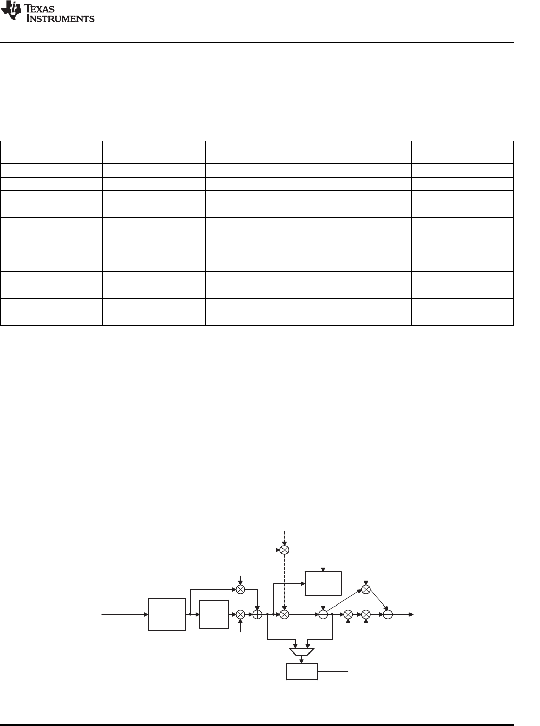
Figure2-16showsthepositioningoftheDRCblockintheTAS5518Cprocessingflow.Asseen,theDRC
inputcancomeeitherbeforeoraftersoftvolumecontrolandloudnessprocessing.
Figure2-16.DRCPositioninginTAS5518CProcessingFlow
SubmitDocumentationFeedbackDescription33
Not Recommended For New Designs
PREVIOUS4567891011121314151617NEXT