System Design Information
MPC5200B Data Sheet, Rev. 1
Freescale Semiconductor 73
For a board with a COP (common on-chip processor) connector, which accesses the JTAG interface and
which needs to reset the JTAG module, simply wiring JTAG_TRST and PORRESET is not recommended.
To reset the MPC5200B via the COP connector, the HRESET pin of the COP should be connected to the
HRESET pin of the MPC5200B. The circuitry shown in Figure 54 allows the COP to assert HRESET or
JTAG_TRST separately, while any other board sources can drive PORRESET.
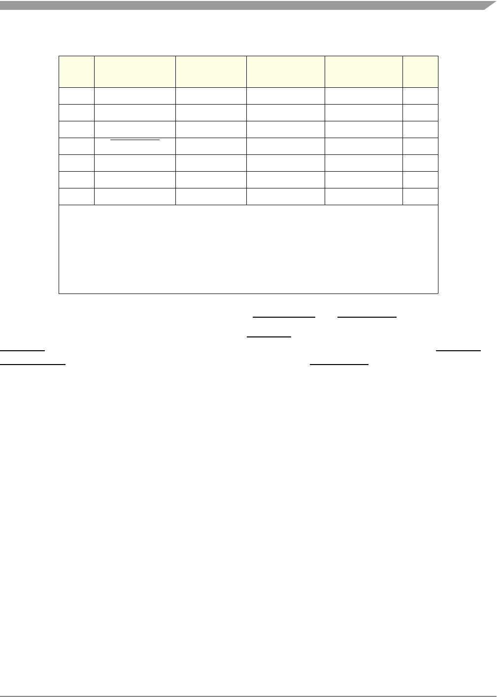
7 JTAG_TCK tck 100k Pull-Up 10k Pull-Up O
6— VDD
(2)
———
5 See Note
(3)
. halted
(3)
——I
4JTAG_TRST
trst 100k Pull-Up 10k Pull-Up O
3 JTAG_TDI tdi 100k Pull-Up 10k Pull-Up O
2 See Note
(4)
. qack
(4)
——O
1JTAG_TDO tdo — — I
NOTES:
1. With respect to the emulator tool’s perspective:
Input is really an output from the embedded e300 core.
Output is really an input to the core.
2. From the board under test, power sense for chip power.
3. HALTED is not available from e300 core.
4. Input to the e300 core to enable/disable soft-stop condition during breakpoints. MPC5200B
internally ties CORE_QACK to GND in its normal/functional mode (always asserted).
Table 53. COP/BDM Interface Signals (continued)
BDM
Pin #
MPC5200B
I/O Pin
BDM
Connector
Internal
Pull Up/Down
External
Pull Up/Down
I/O
(1)


