Freelance Electronics Components Distributor
Closed Dec 25th-26th
800-300-1968
We Stock Hard to Find Parts

SPC5200CBV400B

Part # SPC5200CBV400B
Description MPU MPC52xx RISC 32-Bit 400MHz 2.5V/3.3V 272-Pin BGA Tray
Category IC
Availability Out of Stock
Qty 0
Qty Price
1 + $29.63318


Technical Document


DISCLAIMER: The information provided herein is solely for informational purposes. Customers must be aware of the suitability of this product for their application, and consider that variable factors such as Manufacturer, Product Category, Date Codes, Pictures and Descriptions may differ from available inventory.

MPC5200B Data Sheet, Rev. 1
Electrical and Thermal Characteristics
Freescale Semiconductor40
Figure 24. Timing Diagram—Host Terminating Ultra DMA Data Out Burst
Figure 25. Timing Diagram—Drive Terminating Ultra DMA Data Out Burst
t
LI
DMARQ
(device)
DMACK
(host)
DDMARDY
HSTROBE
DD[0:15]
STOP
(host)
DA0,DA1,DA2,
CS
[0:1]
(host)
(device)
(host)
t
MLI
t
LI
t
LI
t
ACK
t
ACK
t
ACK
t
DVS
t
DVH
t
IORDYZ
t
SS
CRC
DMARQ
(device)
DMACK
(host)
DDMARDY
HSTROBE
DD[0:15]
STOP
(host)
DA0,DA1,DA2,
CS
[0:1]
(host)
t
ACK
t
MLI
(device)
(host)
t
LI
t
MLI
t
LI
t
RP
t
RFS
t
ACK
t
DVH
t
ACK
t
DVS
t
IORDYZ
CRC
Electrical and Thermal Characteristics
MPC5200B Data Sheet, Rev. 1
Freescale Semiconductor 41
Figure 26. Timing Diagram-ATA-ISOLATION
3.3.9 Ethernet
AC Test Timing Conditions:
Output Loading
All Outputs: 25 pF
Table 30. Timing Specification ata_isolation
Sym Description Min Max Units SpecID
1 ata_isolation setup time 7 - IP Bus cycles A8.48
2 ata_isolation hold time - 19 IP Bus cycles A8.49
Table 31. MII Rx Signal Timing
Sym Description Min Max Unit SpecID
t
1
RXD[3:0], RX_DV, RX_ER to RX_CLK setup 10 ns A9.1
t
2
RX_CLK to RXD[3:0], RX_DV, RX_ER hold 10 ns A9.2
t
3
RX_CLK pulse width high 35% 65% RX_CLK Period
(1)
NOTES:
1
RX_CLK shall have a frequency of 25% of data rate of the received signal. See the IEEE 802.3 Specification [6].
A9.3
t
4
RX_CLK pulse width low 35% 65% RX_CLK Period
(1)
A9.4
DIOR
2
1
ATA_ISOLATION
MPC5200B Data Sheet, Rev. 1
Electrical and Thermal Characteristics
Freescale Semiconductor42
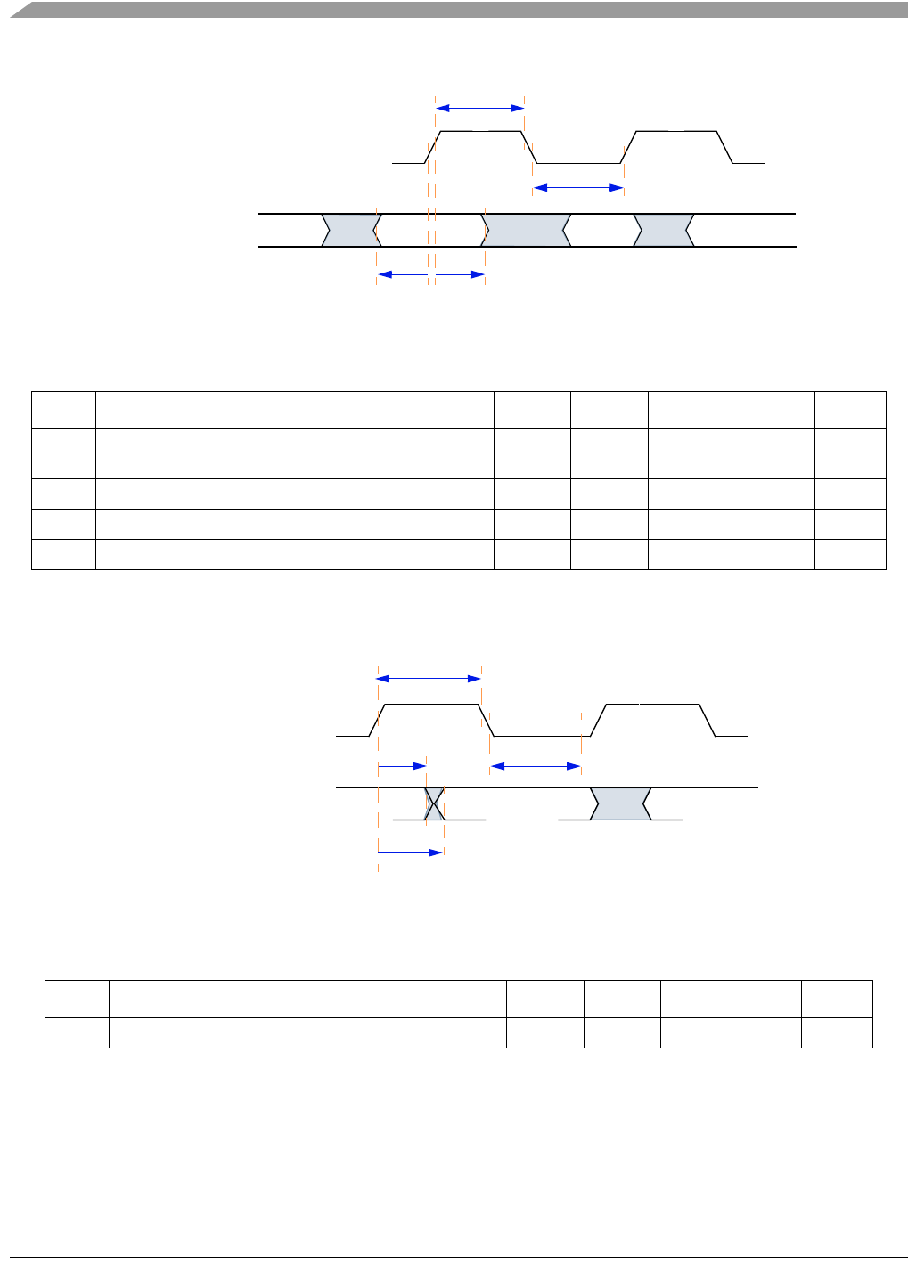
Figure 27. Ethernet Timing Diagram—MII Rx Signal
Figure 28. Ethernet Timing Diagram—MII Tx Signal
Table 32. MII Tx Signal Timing
Sym Description Min Max Unit SpecID
t
5
TX_CLK rising edge to TXD[3:0], TX_EN, TX_ER
invalid
5— ns A9.5
t
6
TX_CLK rising edge to TXD[3:0], TX_EN, TX_ER valid 25 ns A9.6
t
7
TX_CLK pulse width high 35% 65% TX_CLK Period
(1)
NOTES:
1
The TX_CLK frequency shall be 25% of the nominal transmit frequency, e.g., a PHY operating at 100 Mb/s must
provide a TX_CLK frequency of 25 MHz and a PHY operating at 10 Mb/s must provide a TX_CLK frequency of 2.5
MHz. See the IEEE 802.3 Specification [6].
A9.7
t
8
TX_CLK pulse width low 35% 65% TX_CLK Period
(1)
A9.8
Table 33. MII Async Signal Timing
Sym Description Min Max Unit SpecID
t
9
CRS, COL minimum pulse width 1.5 TX_CLK Period A9.9
t
4
t
3
t
1
t
2
RX_CLK (Input)
RXD[3:0] (inputs)
RX_DV
RX_ER
t
8
t
7
t
5
TX_CLK (Input)
TXD[3:0] (Outputs)
TX_EN
TX_ER
t
6
PREVIOUS7891011121314151617181920NEXT