5-499
FAST AND LS TTL DATA
8-INPUT PRIORITY ENCODERS
WITH 3-STATE OUTPUTS
The SN54/74LS348 and the SN54/74LS848 are eight input priority encod-
ers which provide the 8-line to 3-line function.
The outputs (A0–A2) and inputs (0–7) are active low. The active low input
which has the highest priority (input 7 has the highest) is represented on the
outputs (output A0 is the lowest bit). An example would be if inputs 1, 2 and 4
were low, then a binary 4 would be represented on the outputs.
The GS (Group Signal) output is active low when any of the inputs are low. It
serves to indicate when any of the inputs are active.
A0, A1 and A2 are three-state outputs. This allows for up to 64 line expan-
sion without the need for special external circuitry.
A logical one on the Enable Input (EI) forces A0, A1 ared A2 to the disabled
state and outputs GS and EO to the high state. A high on all data inputs (0–7)
together with a low on the EI input disables outputs A0, A1, and A2 and forces
output GS to the high state and output EO to the low state.
Use of the EI input in conjunction with the EO output provides for the capa-
bility of having priority encoding of n input signals.
The LS848 has special internal circuitry providing for a greatly reduced neg-
ative going glitch on the GS (Group Signal) output and on a reduced tendency
for the A0, A1 and A2 outputs to become momentarily enabled. Both of these
occurrences happen when the EI input goes from a logical one to a logical zero
and all data inputs (0–7) are held at logical ones. The internal glitch reduction
circuitry does add an additional fan-in of one on all data inputs (compared to
that of the LS348).
FUNCTION TABLE
INPUTS OUTPUTS
EI 0 1 2 3 4 5 6 7 A2 A1 A0 GS EO
H X X X X X X X X Z Z Z H H
L H H H H H H H H Z Z Z H L
L X X X X X X X L L L L L H
L X X X X X X L H L L H L H
L X X X X X L H H L H L L H
L X X X X L H H H L H H L H
L X X X L H H H H H L L L H
L X X L H H H H H H L H L H
L X L H H H H H H H H L L H
L L H H H H H H H H H H L H
SN54/74LS348
SN54/74LS848
8-INPUT PRIORITY ENCODERS
WITH 3-STATE OUTPUTS
LOW POWER SCHOTTKY
ORDERING INFORMATION
SN54LSXXXJ Ceramic
SN74LSXXXN Plastic
SN74LSXXXD SOIC
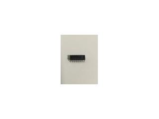
J SUFFIX
CERAMIC
CASE 620-09
N SUFFIX
PLASTIC
CASE 648-08
16
1
16
1
16
1
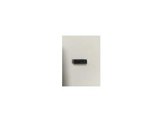
D SUFFIX
SOIC
CASE 751B-03
H = HIGH Logic Level
L = LOW Logic Level
X = Irrelevant
Z = High Impedance State