Closed Dec 25th-26th
800-300-1968
We Stock Hard to Find Parts
My Account
|
My Orders
|
My Cart
Questions?
(800) 300-1968
Register
(current)
My Account
(current)
My Orders
(current)
My Cart
(current)
Categories
(current)
Manufacturers
Request a Quote
Sell Your Excess
Consignment
Quality Assurance
SMP1307-005LF
Part #
SMP1307-005LF
Description
SOT-23 PIN DIODE PB-FREE
Category
IC
Availability
In Stock
Qty
50
Qty
Price
1 +
$0.31962
Manufacturer
Available
Qty
SKYWORKS
Date Code: 0919
Freelance Stock:
50
Ships Immediately
Add to Cart
Related Items
SKYWORKS
IC
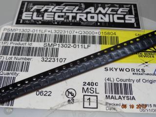
SMP1302-011LF
$0.53985
SKYWORKS
IC
SMP1302-017LF
$1.50075
SKYWORKS
IC
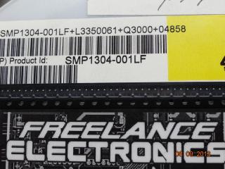
SMP1304-001LF
$1.04470
SKYWORKS
IC
SMP1304-011
$0.65092
SKYWORKS
IC
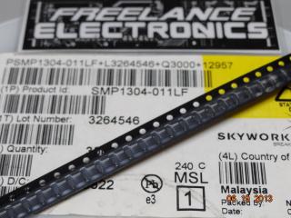
SMP1304-011LF
$0.27324
SKYWORKS
IC
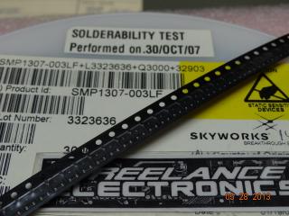
SMP1307-003LF
$0.37519