Freelance Electronics Components Distributor
Closed Dec 25th-26th
800-300-1968
We Stock Hard to Find Parts

SLVU2.8-4.TBT

Part # SLVU2.8-4.TBT
Description TVS DIODE 2.8VWM 15VC 8SOIC
Category IC
Availability In Stock
Qty 45
Qty Price
1 + $0.63013
Manufacturer Available Qty
Semtech Corporation
Date Code: 0834
  • Shipping Freelance Stock: 12
    Ships Immediately
Semtech Corporation
Date Code: 0751
  • Shipping Freelance Stock: 14
    Ships Immediately
Semtech Corporation
Date Code: 0710
  • Shipping Freelance Stock: 7
    Ships Immediately
Semtech Corporation
Date Code: 0940
  • Shipping Freelance Stock: 12
    Ships Immediately


Technical Document


DISCLAIMER: The information provided herein is solely for informational purposes. Customers must be aware of the suitability of this product for their application, and consider that variable factors such as Manufacturer, Product Category, Date Codes, Pictures and Descriptions may differ from available inventory.

PRELIMINARY
1
www.semtech.com
PROTECTION PRODUCTS
SLVU2.8-4
EPD TVS Diode Array
For ESD and Latch-Up Protection
Description
Features
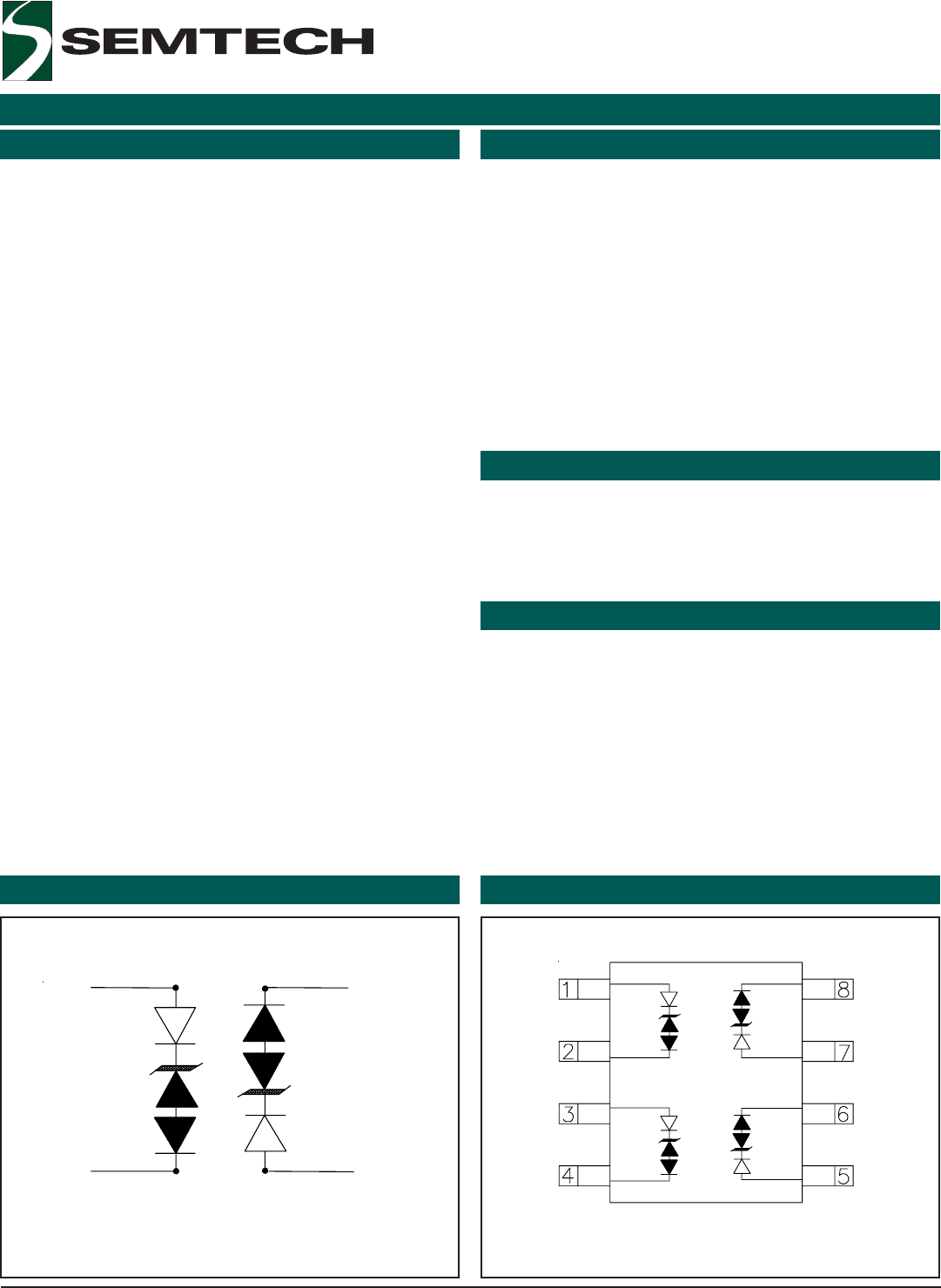
Circuit Diagram Schematic & PIN Configuration
Revision 1/18/2008
The SLV series of transient voltage suppressors are
designed to protect low voltage, state-of-the-art CMOS
semiconductors from transients caused by electro-
static discharge (ESD), cable discharge events (CDE),
lightning and other induced voltage surges.
The devices are constructed using Semtech’s propri-
etary EPD process technology. The EPD process pro-
vides low standoff voltages with significant reductions
in leakage currents and capacitance over silicon-
avalanche diode processes. The SLVU2.8-4 features
integrated low capacitance compensation diodes that
reduce the typical capacitance to 5pF per line. This,
combined with low leakage current, means signal
integrity is preserved in high-speed applications such
as 10/100 Ethernet.
The SLVU2.8-4 is in an SO-8 package and may be used
to protect two high-speed line pairs. The “flow-thru”
design minimizes trace inductance and reduces voltage
overshoot associated with ESD events. The low
clamping voltage of the SLVU2.8-4 minimizes the
stress on the protected IC.
The SLV series TVS diodes will meet the surge require-
ments of IEC 61000-4-2, Level 4.
Applications
Mechanical Characteristics
10/100 Ethernet
WAN/LAN Equipment
Switching Systems
Desktops, Servers, and Notebooks
Instrumentation
Base Stations
Analog Inputs
400 Watts peak pulse power (t
p
= 8/20µs)
Transient protection for high speed data lines to
IEC 61000-4-2 (ESD) ±15kV (air), ±8kV (contact)
IEC 61000-4-4 (EFT) 40A (5/50ns)
IEC 61000-4-5 (Lightning) 24A (8/20µs)
Protects two line pairs (four lines)
Comprehensive pin out for easy board layout
Low capacitance
Low leakage current
Low operating and clamping voltages
Solid-state EPD TVS process technology
JEDEC SO-8 package
Molding compound flammability rating: UL 94V-0
Marking : Part number, date code, logo
Packaging : Tape and Reel
SO-8 (Top View)
Pin 1, 3
Pin 2, 4
Pin 6, 8
Pin 5, 7
22008 Semtech Corp.
www.semtech.com
PROTECTION PRODUCTS
SLVU2.8-4
Absolute Maximum Rating
Electrical Characteristics
gnitaRlobmySeulaVstinU
02/8=pt(rewoPesluPkaeP µ )sP
kp
004sttaW
02/8=pt(tnerruCesluPkaeP µ )sI
PP
42A
)riA(2-4-00016CEIrepDSE
)tcatnoC(2-4-00016CEIrepDSE
V
DSE
52
51
Vk
erutarepmeTgniredloSdaeLT
L
)sdnoces01(062
o
C
erutarepmeTgnitarepOT
J
521+ot55-
o
C
erutarepmeTegarotST
GTS
051+ot55-
o
C
4-8.2UVLS
retemaraPlobmySsnoitidnoCmuminiMlacipyTmumixaMstinU
egatloVffO-dnatSesreveRV
MWR
8.2V
egatloVhguorhT-hcnuPV
TP
I
TP
Aµ2=0.3V
egatloVkcaB-panSV
BS
I
BS
Am05=8.2V
tnerruCegakaeLesreveRI
R
V
MWR
C°52=T,V8.2=
)eniLhcaE(
1Aµ
egatloVgnipmalCV
C
I
PP
t,A2=
p
sµ02/8=
)eniLhcaE(
5.5V
egatloVgnipmalCV
C
I
PP
t,A5=
p
sµ02/8=
)eniLhcaE(
5.8V
egatloVgnipmalCV
C
I
PP
t,A42=
p
sµ02/8=
)eniLhcaE(
51V
ecnaticapaCnoitcnuJC
j
V
R
zHM1=f,V0=
)eniLhcaE(
5Fp
32008 Semtech Corp.
www.semtech.com
PROTECTION PRODUCTS
PRELIMINARY
PROTECTION PRODUCTS
SLVU2.8-4
Typical Characteristics
Non-Repetitive Peak Pulse Power vs. Pulse Time
0
10
20
30
40
50
60
70
80
90
100
110
0 25 50 75 100 125 150
Ambient Temperature - T
A
(
o
C)
% of Rated Power or I
PP
Power Derating Curve
Pulse Waveform Clamping Voltage vs. Peak Pulse Current
0
10
20
30
40
50
60
70
80
90
100
110
0 5 10 15 20 25 30
Time (µs)
Percent of I
PP
e
-t
td = I
PP
/2
0.01
0.1
1
10
0.1 1 10 100 1000
Pulse Duration - t
p
(µs)
Peak Pulse Power - P
pk
(kW)
0
2
4
6
8
10
12
14
0 5 10 15 20 25
Peak Pulse Current - I
PP
(A)
Clamping Voltage - V
C
(V)
Waveform
Parameters:
tr = 8µs
td = 20µs
CH1 S21 LOG 10 dB/
REF 0 dB
START .030 000 MHz STOP 3 000
.
000 000 MHz
Insertion Loss S21Normalized Capacitance vs. Reverse Voltage
0
0.2
0.4
0.6
0.8
1
1.2
1.4
1.6
00.511.522.53
Reverse Voltage - V
R
(V)
C
J
(V
R
) / C
J
(V
R
=0)
f = 1 MHz
123NEXT