5
PI90LV179
3.3V LVDS High-Speed Dierential Line Drivers and Receivers
www.pericom.com 09/25/15 All trademarks are property of their respective owners.
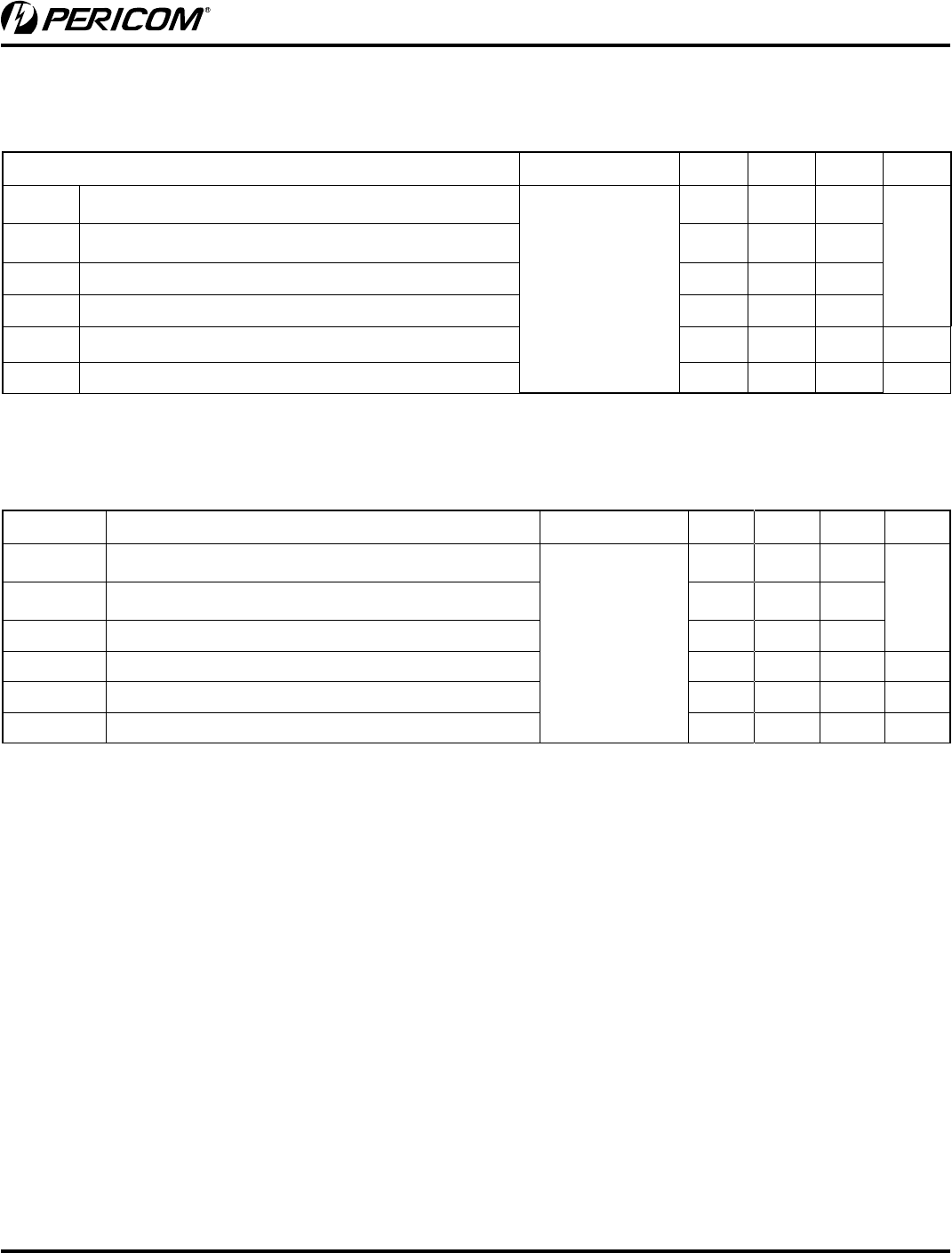
Parameter Test Conditions Min. Typ.
(1)
Max. Units
t
PLH
Propagation delay time, low-to-high-level output
C
L
= 10pF
See Figure 5
2.0 3.1
ns
t
PHL
Propagation delay time, lhigh-to-low-level output 2.2 3.1
t
sk(pp)
(2)
Part-part-part skew
(2)
1.3
t
sk(p)
Pulse skew (t
PHL
– t
PLH
) 300 500 ps
t
r
Output signal rise time 0.9 1.5 ns
t
f
Output signal fall time
1.0 1.8 ns
Receiver Switching Characteristics
(Over recommended operating conditions
unless otherwise noted).
Notes:
1. All typical values are at 25°C with a 3.3V supply
2. t
sk(pp)
: magnitude of difference in propagation delay times between any specic terminals of two devices (all things being equal)
Notes:
1. All typical values are at 25°C with a 3.3V supply.
2. t
sk(pp)
: magnitude of difference in propagation delay times between any specic terminals of two devices (all things being equal).
Parameter Test Conditions Min. Typ.
(1)
Max. Units
t
PLH
Propagation delay time, low-to-high-level output
R
L
= 100 ohms
C
L
= 10pF
See Figure 2
1.9 2.5
ns
t
PHL
Propagation delay time, high-to-low-level output 1.9 2.5
t
r
Differential output signal rise time 0.6 1.1
t
f
Differential output signal fall time
0.6 1.1
t
sk(p)
Pulse skew (t
PHL
- t
PLH
) 270 ps
t
sk(pp)
Part-part-part skew
(2)
0.9
ns
Driver Switching Characteristics
(Over recommended operating conditions
unless otherwise noted).


