3
PI90LV179
3.3V LVDS High-Speed Dierential Line Drivers and Receivers
www.pericom.com 09/25/15 All trademarks are property of their respective owners.
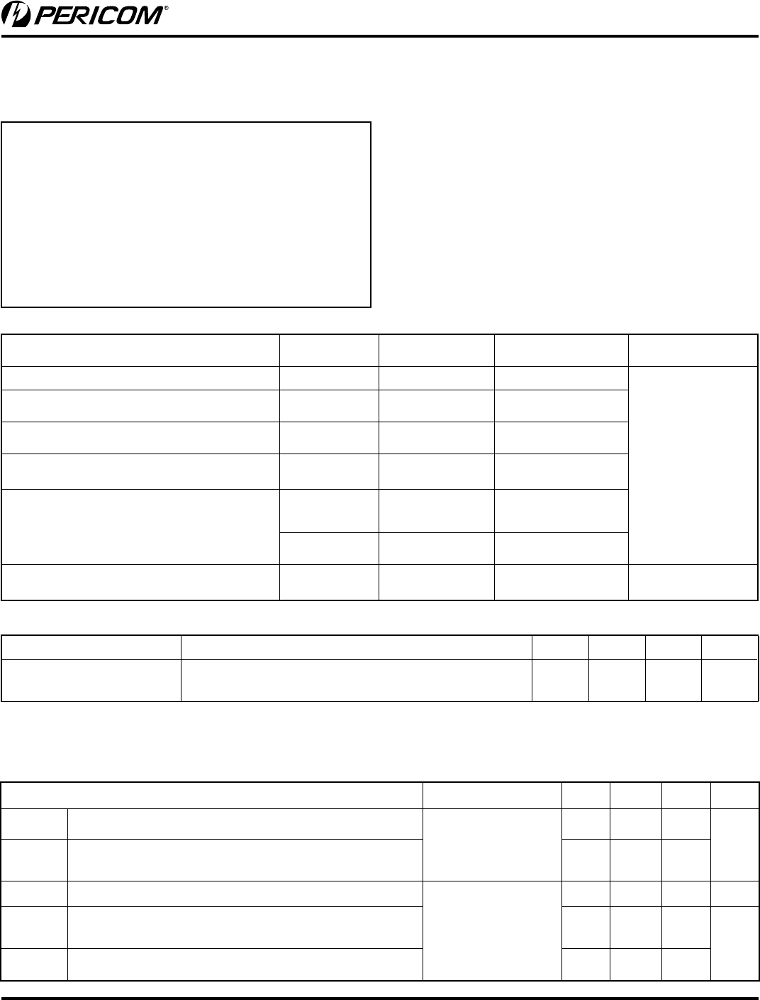
Parameter Test Condition Min. Typ.
(1)
Max. Units
I
CC
(2)
Supply
Current
No receiver load, Driver R
L
= 100 ohms 8.0 10.8 mA
Electrical Characteristics
(Over recommended operating conditions
unless otherwise noted).
Electrical Characteristics
(Over recommended operating conditions
unless otherwise noted).
Parameter Test Conditions Min. Typ. Max. Units
|
V
OD
|
Differential output voltage magnitude
R
L
= 100 ohms
See Figures 1 and 2
247 390 470
mV
D|
V
OD
|
Change in differential output voltage magnitude between
logic states
–50 50
V
OC(SS)
Steady-state common-mode output voltage
See Figure 3
1.125 1.25 1.375 V
D
V
OC(SS)
Change in steady-state common-mode output voltage
between logic states
–50 50
mV
V
OC(PP)
Peak-to-peak common-mode output voltage 50 150
Notes:
1. All typical values are at 25°C with a 3.3V supply
2. I
CC
measured with all TTL input. V
IN
= V
CC
or GND.
Absolute Maximum Ratings
Supply Voltage (V
CC
) ....................................... –0.5V to +4.0V
Driver
Input Voltage (D
IN
) .......................... –0.3V to (Vcc + 0.3V)
Output Voltage (D
OUT+
, D
OUT-
) ....................... –0.3V to +3.9V
Short Circuit Duration (D
OUT+
, D
OUT-
) ..................Continuous
Receiver
Input Voltage (R
IN+
, R
IN-
) .............................. –0.3V to +3.9V
Output Voltage (R
OUT
) ........................–0.3V to (V
CC
+ 0.3V)
Storage Temperature Range ......................... –65°C to +150°C
ESD Rating.............................................................. 2kV HBM
Min. Typ. Max. Units
Supply Voltage (V
CC
) 3 3.3 3.6
V
High Level Input Voltage, V
IH
2
Low Level Input Voltage, V
IL
0.8
Magnitude of Differential Inpu
t
Voltage V
ID
0.1 0.6
Common-mode Input Voltage,
V
IC
(Fig 5)
|V
ID
|
/2
2.4
– |V
ID
|
/2
V
CC
–0.8
Operating Free Air Temperature
T
A
–40 85 °C
Recommended Operating Conditions
Note: Stresses greater than those listed under MAXIMUM
RATINGS may cause permanent damage to the device. is is a
stress rating only and functional operation of the device at these
or any other conditions above those indicated in the operational
sections of this specication is not implied. Exposure to absolute
maximum rating conditions for extended periods may aect
reliability.


