Closed Dec 25th-26th
800-300-1968
We Stock Hard to Find Parts
My Account
|
My Orders
|
My Cart
Questions?
(800) 300-1968
Register
(current)
My Account
(current)
My Orders
(current)
My Cart
(current)
Categories
(current)
Manufacturers
Request a Quote
Sell Your Excess
Consignment
Quality Assurance
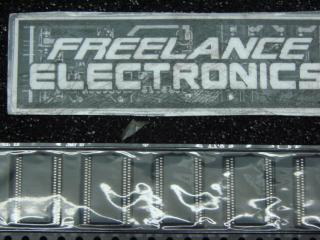
PCK2001MDB
Part #
PCK2001MDB
Description
Clock Buffer PII CLCK DRVR MOBILE
Category
IC
Availability
In Stock
Qty
580
Qty
Price
1 - 121
$1.65738
122 - 243
$1.31837
244 - 365
$1.24303
366 - 487
$1.15514
488 +
$1.02958
Manufacturer
Available
Qty
Philips Semiconductor
Date Code: 9822
Freelance Stock:
94
Ships Immediately
Philips Semiconductor
Date Code: 9822
Freelance Stock:
47
Ships Immediately
Philips Semiconductor
Date Code: 9822
Freelance Stock:
187
Ships Immediately
Philips Semiconductor
Date Code: 9814
Freelance Stock:
64
Ships Immediately
Philips Semiconductor
Date Code: 9822
Freelance Stock:
47
Ships Immediately
Philips Semiconductor
Date Code: 9822
Freelance Stock:
141
Ships Immediately
Add to Cart
Related Items
NXP SEMICONDUCTORS
IC
PCK2001DL
Philips Semiconductor
IC
PCK2001RDB
$3.77630
Philips Semiconductor
IC
PCK2002B
Philips Semiconductor
IC
PCK2002BDL
Philips Semiconductor
IC
PCK2002DGG
Philips Semiconductor
IC
PCK2002DL