Closed Dec 25th-26th
800-300-1968
We Stock Hard to Find Parts
My Account
|
My Orders
|
My Cart
Questions?
(800) 300-1968
Register
(current)
My Account
(current)
My Orders
(current)
My Cart
(current)
Categories
(current)
Manufacturers
Request a Quote
Sell Your Excess
Consignment
Quality Assurance
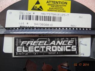
MAX7375AXR105+T
Part #
MAX7375AXR105+T
Description
LEAD FREE
Category
IC
Availability
Out of Stock
Qty
0
Qty
Price
1 +
$0.40000
Related Items
MAXIM
IC
MAX7312AWG
$6.53428
MAXIM
IC
MAX732CPA
$3.05920
MAXIM
IC
MAX735EPA
$6.17780
MAXIM
IC
MAX7375AXR105+
$4.86937
MAXIM
IC
MAX7375AXR105-T
$0.64288
MAXIM
IC
MAX738ACWE-T
$4.59260