Closed Dec 25th-26th
800-300-1968
We Stock Hard to Find Parts
My Account
|
My Orders
|
My Cart
Questions?
(800) 300-1968
Register
(current)
My Account
(current)
My Orders
(current)
My Cart
(current)
Categories
(current)
Manufacturers
Request a Quote
Sell Your Excess
Consignment
Quality Assurance
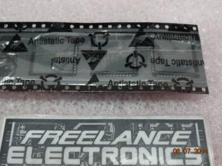
MAX241ECAI
Part #
MAX241ECAI
Description
IC TX W/RCVR RS232 5V 28-SSOP
Category
IC
Availability
In Stock
Qty
74
Qty
Price
1 - 15
$12.42248
16 - 31
$9.88152
32 - 46
$9.31686
47 - 62
$8.65809
63 +
$7.71700
Manufacturer
Available
Qty
MAXIM
Date Code: 0641
Freelance Stock:
26
Ships Immediately
MAXIM
Date Code: 0641
Freelance Stock:
48
Ships Immediately
Add to Cart
Related Items
MAXIM
IC
MAX241EEAI
$17.31534
MAXIM
IC
MAX242CPN
$2.73007
MAXIM
IC
MAX242CWN
$0.57000
MAXIM
IC
MAX242EDJN
$11.02090
MAXIM
IC
MAX242EWN
$2.94047
MAXIM
IC
MAX248EQH
$9.75000