17
LTC1538-AUX/LTC1539
APPLICATIONS INFORMATION
WUU
U
(DC) and the V
OSENSE2
pin is connected to the feedback
resistors as shown in Figure 5b. Controller 2 will force the
externally attenuated output voltage to 1.19V.
Power-On Reset Function (POR)
The power-on reset function monitors the output voltage
of the first controller and turns on an open drain device
when it is below its properly regulated voltage. An external
pull-up resistor is required on the POR1 pin.
When power is first applied or when coming out of
shutdown, the POR1 output is held at ground. When the
output voltage rises above a level which is 5% below the final
regulated output value, an internal counter starts. After this
counter counts 2
16
(65536) clock cycles, the POR1 pull-
down device turns off. The POR1 output is active when both
controllers are shut down as long as V
IN
is powered.
The POR1 output will go low whenever the output voltage
of the first controller drops below 7.5% of its regulated
value for longer than approximately 30µs, signaling an
out-of-regulation condition. In shutdown, when RUN/SS1
and RUN/SS2 are both below 1.3V, the POR1 output is
pulled low even if the regulator’s output is held up by an
external source.
RUN/Soft Start Function
The RUN/SS1 and RUN/SS2 pins each serve two func-
tions. Each pin provides the soft start function and a
means to shut down each controller. Soft start reduces
surge currents from V
IN
by providing a gradual ramp-up of
the internal current limit.
Power supply sequencing
can
also be accomplished using this pin.
An internal 3µA current source charges up an external
capacitor C
SS.
When the voltage on RUN/SS1 (RUN/SS2)
reaches 1.3V the particular controller is permitted to start
operating. As the voltage on the pin continues to ramp
from 1.3V to 2.4V, the internal current limit is also ramped
at a proportional linear rate. The current limit begins at
approximately 50mV/R
SENSE
(at V
RUN/SS
= 1.3V) and ends
at 150mV/R
SENSE
(V
RUN/SS
≥ 2.7V). The output current
thus ramps up slowly, reducing the starting surge current
required from the input power supply. If RUN/SS has been
pulled all the way to ground there is a delay before starting
of approximately 500ms/µF, followed by a similar time to
reach full current on that controller.
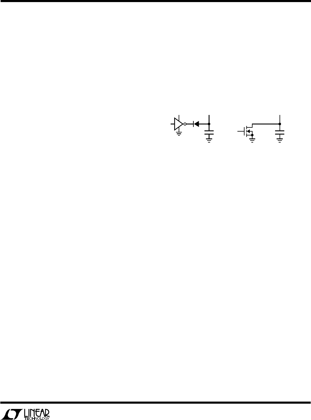
By pulling both RUN/SS controller pins below 1.3V, the
LTC1538-AUX/LTC1539 are put into shutdown
(I
Q
< 200µA). These pins can be driven directly from logic
as shown in Figure 6. Diode D1 in Figure 6 reduces the start
delay but allows C
SS
to ramp up slowly providing the soft
start function; this diode and C
SS
can be deleted if soft start
is not needed. Each RUN/SS pin has an internal 6V Zener
clamp (See Functional Diagram).
Foldback Current Limiting
As described in Power MOSFET and D1 Selection, the
worst-case dissipation for either MOSFET occurs with a
short-circuited output, when the synchronous MOSFET
conducts the current limit value almost continuously. In
most applications this will not cause excessive heating,
even for extended fault intervals. However, when heat
sinking is at a premium or higher R
DS(ON)
MOSFETs are
being used, foldback current limiting should be added to
reduce the current in proportion to the severity of the fault.
Foldback current limiting is implemented by adding diode
D
FB
between the output and the I
TH
pin as shown in the
Functional Diagram. In a hard short (V
OUT
= 0V) the
current will be reduced to approximately 25% of the
maximum output current. This technique may be used for
all applications with regulated output voltages of 1.8V or
greater.
D1
C
SS
3.3V
OR 5V
RUN/SS1
(RUN/SS2)
C
SS
1538 F06
RUN/SS1
(RUN/SS2)
Figure 6. RUN/SS Pin Interfacing


