Freelance Electronics Components Distributor
Closed Dec 25th-26th
800-300-1968
We Stock Hard to Find Parts

LM2574HVN-5.0

Part # LM2574HVN-5.0
Description IC REG BUCK 5V 0.5A 8-DIP
Category IC
Availability Out of Stock
Qty 0
Qty Price
1 + $1.41000


Technical Document


DISCLAIMER: The information provided herein is solely for informational purposes. Customers must be aware of the suitability of this product for their application, and consider that variable factors such as Manufacturer, Product Category, Date Codes, Pictures and Descriptions may differ from available inventory.

LM2574, LM2574HV
www.ti.com
SNVS104C JUNE 1999REVISED APRIL 2013
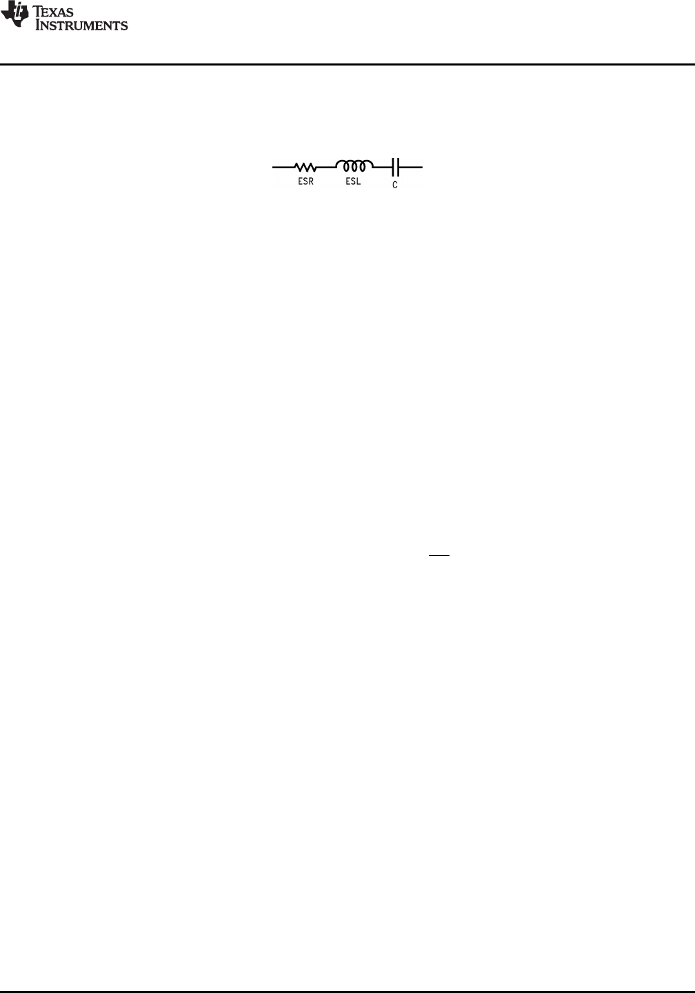
CAPACITOR EQUIVALENT SERIES RESISTANCE (ESR)
The purely resistive component of a real capacitor's impedance (see Figure 37). It causes power loss resulting in
capacitor heating, which directly affects the capacitor's operating lifetime. When used as a switching regulator
output filter, higher ESR values result in higher output ripple voltages.
Figure 37. Simple Model of a Real Capacitor
Most standard aluminum electrolytic capacitors in the 100 μF–1000 μF range have 0.5Ω to 0.1Ω ESR. Higher-
grade capacitors (“low-ESR”, “high-frequency”, or low-inductance”) in the 100 μF–1000 μF range generally have
ESR of less than 0.15Ω.
EQUIVALENT SERIES INDUCTANCE (ESL)
The pure inductance component of a capacitor (see Figure 37). The amount of inductance is determined to a
large extent on the capacitor's construction. In a buck regulator, this unwanted inductance causes voltage spikes
to appear on the output.
OUTPUT RIPPLE VOLTAGE
The AC component of the switching regulator's output voltage. It is usually dominated by the output capacitor's
ESR multiplied by the inductor's ripple current (ΔI
IND
). The peak-to-peak value of this sawtooth ripple current can
be determined by readingINDUCTOR RIPPLE CURRENT (ΔI
IND
) of Application Hints.
CAPACITOR RIPPLE CURRENT
RMS value of the maximum allowable alternating current at which a capacitor can be operated continuously at a
specified temperature.
STANDBY QUIESCENT CURRENT (I
STBY
)
Supply current required by the LM2574 when in the standby mode (ON/OFF pin is driven to TTL-high voltage,
thus turning the output switch OFF).
INDUCTOR RIPPLE CURRENT (ΔI
IND
)
The peak-to-peak value of the inductor current waveform, typically a sawtooth waveform when the regulator is
operating in the continuous mode (vs. discontinuous mode).
CONTINUOUS/DISCONTINUOUS MODE OPERATION
Relates to the inductor current. In the continuous mode, the inductor current is always flowing and never drops to
zero, vs. the discontinuous mode, where the inductor current drops to zero for a period of time in the normal
switching cycle.
INDUCTOR SATURATION
The condition which exists when an inductor cannot hold any more magnetic flux. When an inductor saturates,
the inductor appears less inductive and the resistive component dominates. Inductor current is then limited only
by the DC resistance of the wire and the available source current.
OPERATING VOLT MICROSECOND CONSTANT (E•T
op
)
The product (in VoIt•μs) of the voltage applied to the inductor and the time the voltage is applied. This E•T
op
constant is a measure of the energy handling capability of an inductor and is dependent upon the type of core,
the core area, the number of turns, and the duty cycle.
Copyright © 1999–2013, Texas Instruments Incorporated Submit Documentation Feedback 25
Product Folder Links: LM2574 LM2574HV
LM2574, LM2574HV
SNVS104C JUNE 1999REVISED APRIL 2013
www.ti.com
REVISION HISTORY
Changes from Revision B (April 2013) to Revision C Page
Changed layout of National Data Sheet to TI format .......................................................................................................... 25
26 Submit Documentation Feedback Copyright © 1999–2013, Texas Instruments Incorporated
Product Folder Links: LM2574 LM2574HV
PACKAGE OPTION ADDENDUM
www.ti.com
11-Apr-2013
Addendum-Page 1
PACKAGING INFORMATION
Orderable Device Status
(1)
Package Type Package
Drawing
Pins Package
Qty
Eco Plan
(2)
Lead/Ball Finish MSL Peak Temp
(3)
Op Temp (°C) Top-Side Markings
(4)
Samples
LM2574HVM-12 ACTIVE SOIC NPA 14 50 TBD Call TI Call TI -40 to 125 LM2574HVM
-12 P+
LM2574HVM-12/NOPB ACTIVE SOIC NPA 14 50 Green (RoHS
& no Sb/Br)
CU SN Level-3-260C-168 HR -40 to 125 LM2574HVM
-12 P+
LM2574HVM-15 ACTIVE SOIC NPA 14 50 TBD Call TI Call TI -40 to 125 LM2574HVM
-15 P+
LM2574HVM-15/NOPB ACTIVE SOIC NPA 14 50 Green (RoHS
& no Sb/Br)
CU SN Level-3-260C-168 HR -40 to 125 LM2574HVM
-15 P+
LM2574HVM-3.3 ACTIVE SOIC NPA 14 50 TBD Call TI Call TI -40 to 125 LM2574HVM
-3.3 P+
LM2574HVM-3.3/NOPB ACTIVE SOIC NPA 14 50 Green (RoHS
& no Sb/Br)
CU SN Level-3-260C-168 HR -40 to 125 LM2574HVM
-3.3 P+
LM2574HVM-5.0 ACTIVE SOIC NPA 14 50 TBD Call TI Call TI -40 to 125 LM2574HVM
-5.0 P+
LM2574HVM-5.0/NOPB ACTIVE SOIC NPA 14 50 Green (RoHS
& no Sb/Br)
CU SN Level-3-260C-168 HR -40 to 125 LM2574HVM
-5.0 P+
LM2574HVM-ADJ ACTIVE SOIC NPA 14 50 TBD Call TI Call TI -40 to 125 LM2574HVM
-ADJ P+
LM2574HVM-ADJ/NOPB ACTIVE SOIC NPA 14 50 Green (RoHS
& no Sb/Br)
CU SN Level-3-260C-168 HR -40 to 125 LM2574HVM
-ADJ P+
LM2574HVMX-12/NOPB ACTIVE SOIC NPA 14 1000 Green (RoHS
& no Sb/Br)
CU SN Level-3-260C-168 HR -40 to 125 LM2574HVM
-12 P+
LM2574HVMX-15 ACTIVE SOIC NPA 14 1000 TBD Call TI Call TI -40 to 125 LM2574HVM
-15 P+
LM2574HVMX-15/NOPB ACTIVE SOIC NPA 14 1000 Green (RoHS
& no Sb/Br)
CU SN Level-3-260C-168 HR -40 to 125 LM2574HVM
-15 P+
LM2574HVMX-3.3 ACTIVE SOIC NPA 14 1000 TBD Call TI Call TI -40 to 125 LM2574HVM
-3.3 P+
LM2574HVMX-3.3/NOPB ACTIVE SOIC NPA 14 1000 Green (RoHS
& no Sb/Br)
CU SN Level-4-260C-72 HR -40 to 125 LM2574HVM
-3.3 P+
LM2574HVMX-5.0 ACTIVE SOIC NPA 14 1000 TBD Call TI Call TI -40 to 125 LM2574HVM
-5.0 P+
LM2574HVMX-5.0/NOPB ACTIVE SOIC NPA 14 1000 Green (RoHS
& no Sb/Br)
CU SN Level-3-260C-168 HR -40 to 125 LM2574HVM
-5.0 P+
PREVIOUS23456789101112NEXT