Freelance Electronics Components Distributor
Closed Dec 25th-26th
800-300-1968
We Stock Hard to Find Parts

LM2574HVN-5.0

Part # LM2574HVN-5.0
Description IC REG BUCK 5V 0.5A 8-DIP
Category IC
Availability Out of Stock
Qty 0
Qty Price
1 + $1.41000


Technical Document


DISCLAIMER: The information provided herein is solely for informational purposes. Customers must be aware of the suitability of this product for their application, and consider that variable factors such as Manufacturer, Product Category, Date Codes, Pictures and Descriptions may differ from available inventory.

LM2574, LM2574HV
SNVS104C JUNE 1999REVISED APRIL 2013
www.ti.com
For an input voltage of 8V or more, the maximum available output current in this configuration is approximately
100 mA. At lighter loads, the minimum input voltage required drops to approximately 4.7V.
The switch currents in this buck-boost configuration are higher than in the standard buck-mode design, thus
lowering the available output current. Also, the start-up input current of the buck-boost converter is higher than
the standard buck-mode regulator, and this may overload an input power source with a current limit less than
0.6A. Using a delayed turn-on or an undervoltage lockout circuit (described in the next section) would allow the
input voltage to rise to a high enough level before the switcher would be allowed to turn on.
Because of the structural differences between the buck and the buck-boost regulator topologies, the LM2574
Series Buck Regulator Design Procedure can not be used to select the inductor or the output capacitor. The
recommended range of inductor values for the buck-boost design is between 68 μH and 220 μH, and the output
capacitor values must be larger than what is normally required for buck designs. Low input voltages or high
output currents require a large value output capacitor (in the thousands of micro Farads).
The peak inductor current, which is the same as the peak switch current, can be calculated from the following
formula:
where
f
osc
= 52 kHz. Under normal continuous inductor current operating conditions,
the minimum V
IN
represents the worst case. Select an inductor that is rated for the peak current anticipated.
(6)
Also, the maximum voltage appearing across the regulator is the absolute sum of the input and output voltage.
For a 12V output, the maximum input voltage for the LM2574 is +28V, or +48V for the LM2574HV.
The Switchers Made Simple version 3.3) design software can be used to determine the feasibility of regulator
designs using different topologies, different input-output parameters, different components, etc.
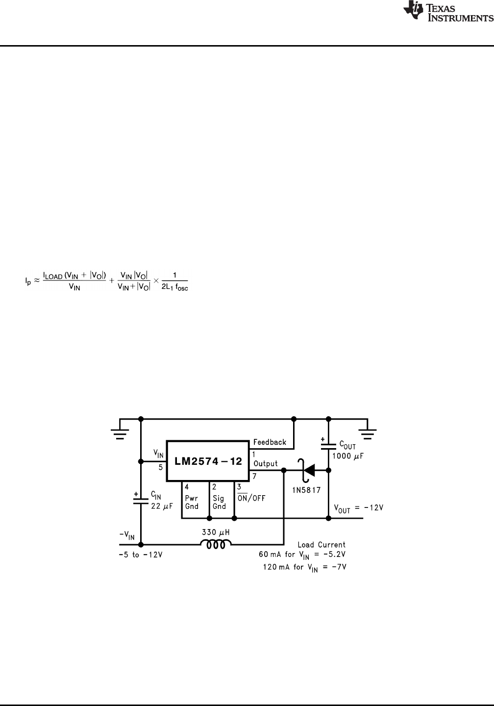
NEGATIVE BOOST REGULATOR
Another variation on the buck-boost topology is the negative boost configuration. The circuit in Figure 32 accepts
an input voltage ranging from 5V to 12V and provides a regulated 12V output. Input voltages greater than
12V will cause the output to rise above 12V, but will not damage the regulator.
Note: Pin numbers are for 8-pin PDIP package.
Figure 32. Negative Boost
Because of the boosting function of this type of regulator, the switch current is relatively high, especially at low
input voltages. Output load current limitations are a result of the maximum current rating of the switch. Also,
boost regulators can not provide current limiting load protection in the event of a shorted load, so some other
means (such as a fuse) may be necessary.
22 Submit Documentation Feedback Copyright © 1999–2013, Texas Instruments Incorporated
Product Folder Links: LM2574 LM2574HV
LM2574, LM2574HV
www.ti.com
SNVS104C JUNE 1999REVISED APRIL 2013
UNDERVOLTAGE LOCKOUT
In some applications it is desirable to keep the regulator off until the input voltage reaches a certain threshold. An
undervoltage lockout circuit which accomplishes this task is shown in Figure 33 while Figure 34 shows the same
circuit applied to a buck-boost configuration. These circuits keep the regulator off until the input voltage reaches
a predetermined level.
V
TH
V
Z1
+ 2V
BE
(Q1)
Note: Complete circuit not shown (see Figure 31).
Note: Pin numbers are for 8-pin PDIP package.
Figure 33. Undervoltage Lockout for Buck Circuit
Note: Complete circuit not shown (see Figure 31 ).
Note: Pin numbers are for 8-pin PDIP package.
Figure 34. Undervoltage Lockout
for Buck-Boost Circuit
DELAYED STARTUP
The ON /OFF pin can be used to provide a delayed startup feature as shown in Figure 35. With an input voltage
of 20V and for the part values shown, the circuit provides approximately 10 ms of delay time before the circuit
begins switching. Increasing the RC time constant can provide longer delay times. But excessively large RC time
constants can cause problems with input voltages that are high in 60 Hz or 120 Hz ripple, by coupling the ripple
into the ON /OFF pin.
ADJUSTABLE OUTPUT, LOW-RIPPLE POWER SUPPLY
A 500 mA power supply that features an adjustable output voltage is shown in Figure 36. An additional L-C filter
that reduces the output ripple by a factor of 10 or more is included in this circuit.
Copyright © 1999–2013, Texas Instruments Incorporated Submit Documentation Feedback 23
Product Folder Links: LM2574 LM2574HV
LM2574, LM2574HV
SNVS104C JUNE 1999REVISED APRIL 2013
www.ti.com
Note: Complete circuit not shown.
Note: Pin numbers are for 8-pin PDIP package.
Figure 35. Delayed Startup
Note: Pin numbers are for 8-pin PDIP package.
Figure 36. 1.2V to 55V Adjustable 500 mA Power Supply with Low Output Ripple
Definition of Terms
BUCK REGULATOR
A switching regulator topology in which a higher voltage is converted to a lower voltage. Also known as a step-
down switching regulator.
BUCK-BOOST REGULATOR
A switching regulator topology in which a positive voltage is converted to a negative voltage without a
transformer.
DUTY CYCLE (D)
Ratio of the output switch's on-time to the oscillator period.
(7)
CATCH DIODE OR CURRENT STEERING DIODE
The diode which provides a return path for the load current when the LM2574 switch is OFF.
EFFICIENCY (η)
The proportion of input power actually delivered to the load.
(8)
24 Submit Documentation Feedback Copyright © 1999–2013, Texas Instruments Incorporated
Product Folder Links: LM2574 LM2574HV
PREVIOUS123456789101112NEXT