Freelance Electronics Components Distributor
Closed Dec 25th-26th
800-300-1968
We Stock Hard to Find Parts

LM2574HVN-5.0

Part # LM2574HVN-5.0
Description IC REG BUCK 5V 0.5A 8-DIP
Category IC
Availability Out of Stock
Qty 0
Qty Price
1 + $1.41000


Technical Document


DISCLAIMER: The information provided herein is solely for informational purposes. Customers must be aware of the suitability of this product for their application, and consider that variable factors such as Manufacturer, Product Category, Date Codes, Pictures and Descriptions may differ from available inventory.

LM2574, LM2574HV
SNVS104C JUNE 1999REVISED APRIL 2013
www.ti.com
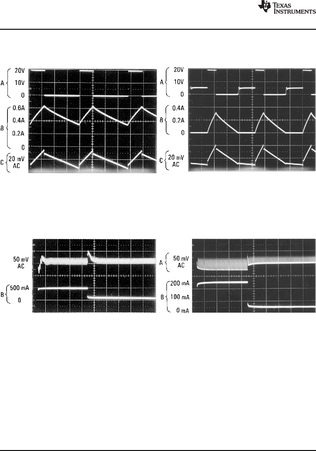
Typical Performance Characteristics
(Circuit of Figure 24)
Continuous Mode Switching Waveforms Discontinuous Mode Switching Waveforms
V
OUT
= 5V, 500 mA Load Current, L = 330 μH V
OUT
= 5V, 100 mA Load Current, L = 100 μH
Notes: Notes:
A: Output Pin Voltage, 10V/div A: Output Pin Voltage, 10V/div
B: Inductor Current, 0.2 A/div B: Inductor Current, 0.2 A/div
C: Output Ripple Voltage, 20 mV/div, C: Output Ripple Voltage, 20 mV/div,
AC-Coupled AC-Coupled
Horizontal Time Base: 5 μs/div Horizontal Time Base: 5 μs/div
Figure 18. Figure 19.
500 mA Load Transient Response for Continuous 250 mA Load Transient Response for Discontinuous
Mode Operation. L = 330 μH, C
OUT
= 300 μF Mode Operation. L = 68 μH, C
OUT
= 470 μF
Notes:
Notes:
A: Output Voltage, 50 mV/div.
AC Coupled
AC Coupled
B: 100 mA to 500 mA Load Pulse
B: 50 mA to 250 mA Load Pulse
Horizontal Time Base: 200 μs/div
Figure 20. Figure 21.
10 Submit Documentation Feedback Copyright © 1999–2013, Texas Instruments Incorporated
Product Folder Links: LM2574 LM2574HV
LM2574, LM2574HV
www.ti.com
SNVS104C JUNE 1999REVISED APRIL 2013
Block Diagram
R1 = 1k
3.3V, R2 = 1.7k
5V, R2 = 3.1k
12V, R2 = 8.84k
15V, R2 = 11.3k
For Adj. Version
R1 = Open, R2 = 0Ω
Note: Pin numbers are for the 8-pin PDIP package.
Figure 22.
Test Circuit and Layout Guidelines
C
IN
— 22 μF, 75V
Aluminum Electrolytic
C
OUT
— 220 μF, 25V
Aluminum Electrolytic
D1 — Schottky, 11DQ06
L1 — 330 μH, 52627
(for 5V in, 3.3V out, use
100 μH, RL-1284-100)
R1 — 2k, 0.1%
R2 — 6.12k, 0.1%
Figure 23. Fixed Output Voltage Versions
Copyright © 1999–2013, Texas Instruments Incorporated Submit Documentation Feedback 11
Product Folder Links: LM2574 LM2574HV
LM2574, LM2574HV
SNVS104C JUNE 1999REVISED APRIL 2013
www.ti.com
Figure 24. Adjustable Output Voltage Version
As in any switching regulator, layout is very important. Rapidly switching currents associated with wiring
inductance generate voltage transients which can cause problems. For minimal inductance and ground loops, the
length of the leads indicated by heavy lines should be kept as short as possible. Single-point grounding (as
indicated) or ground plane construction should be used for best results. When using the Adjustable version,
physically locate the programming resistors near the regulator, to keep the sensitive feedback wiring short.
Table 1. Inductor Selection by Manufacturer's Part Number
Inductor Value Pulse Eng. Renco NPI
68 μH * RL-1284-68-43 NP5915
100 μH * RL-1284-100-43 NP5916
150 μH 52625 RL-1284-150-43 NP5917
220 μH 52626 RL-1284-220-43 NP5918/5919
330 μH 52627 RL-1284-330-43 NP5920/5921
470 μH 52628 RL-1284-470-43 NP5922
680 μH 52629 RL-1283-680-43 NP5923
1000 μH 52631 RL-1283-1000-43 *
1500 μH * RL-1283-1500-43 *
2200 μH * RL-1283-2200-43 *
12 Submit Documentation Feedback Copyright © 1999–2013, Texas Instruments Incorporated
Product Folder Links: LM2574 LM2574HV
PREVIOUS12345678910NEXT