3
®
INA132
SPECIFICATIONS: V
S
= +5V
At T
A
= +25°C, V
S
= +5V, R
L
= 10kΩ connected to V
S
/2, and Reference Pin connected to V
S
/2, unless otherwise noted.
INA132P, U INA132PA, UA
PARAMETER CONDITIONS MIN TYP MAX MIN TYP MAX UNITS
OFFSET VOLTAGE
(1)
RTO
Initial ±150 ±500 ✽ ±750 µV
vs Temperature ±2 ✽ µV/°C
INPUT VOLTAGE RANGE
Common-Mode Voltage Range 0 2(V+)–2 ✽✽V
Common-Mode Rejection V
CM
= 0V to 8V, R
S
= 0Ω 76 90 70 ✽ dB
OUTPUT
Voltage, Positive R
L
= 100kΩ (V+)–1 (V+)–0.75 ✽✽ V
Negative R
L
= 100kΩ +0.25 +0.06 ✽✽ V
Positive R
L
= 10kΩ (V+)–1 (V+)–0.8 ✽✽ V
Negative R
L
= 10kΩ +0.25 +0.12 ✽✽ V
POWER SUPPLY
Rated Voltage +5 ✽ V
Voltage Range +2.7 +36 ✽✽V
Quiescent Current I
O
= 0mA ±155 ±185 ✽✽ µA
✽Specifications the same as INA132P.
NOTE: (1) Include effects of amplifier’s input bias and offset currents.
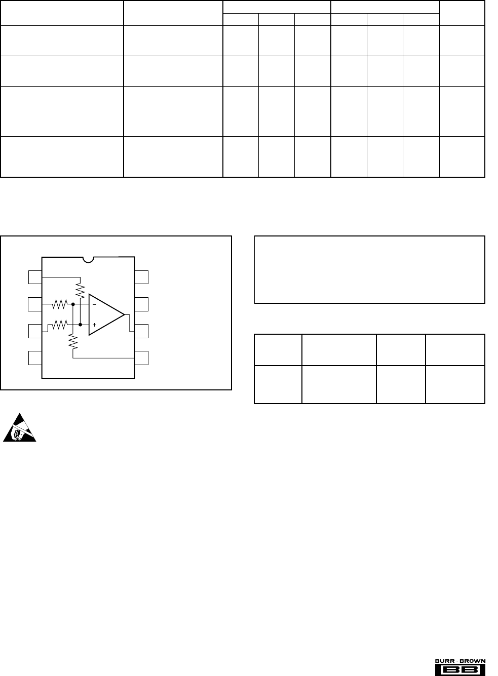
PIN CONFIGURATION
TOP VIEW DIP/SOIC
Ref
–In
+In
V–
No Internal Connection
V+
Output
Sense
1
2
3
4
8
7
6
5
Supply Voltage, V+ to V– .................................................................... 36V
Input Voltage Range .......................................................................... ±80V
Output Short-Circuit (to ground) .............................................. Continuous
Operating Temperature ................................................. –55°C to +125°C
Storage Temperature..................................................... –55°C to +125°C
Junction Temperature .................................................................... +150°C
Lead Temperature (soldering, 10s) ............................................... +300°C
ABSOLUTE MAXIMUM RATINGS
ORDERING INFORMATION
PACKAGE
DRAWING TEMPERATURE
PRODUCT PACKAGE NUMBER
(1)
RANGE
INA132PA 8-Pin Plastic DIP 006 –40°C to +85°C
INA132P 8-Pin Plastic DIP 006 –40°C to +85°C
INA132UA SO-8 Surface-Mount 182 –40°C to +85°C
INA132U SO-8 Surface-Mount 182 –40°C to +85°C
NOTE: (1) For detailed drawing and dimension table, please see end of data
sheet, or Appendix C of Burr-Brown IC Data Book.
ELECTROSTATIC
DISCHARGE SENSITIVITY
This integrated circuit can be damaged by ESD. Burr-Brown
recommends that all integrated circuits be handled with ap-
propriate precautions. Failure to observe proper handling and
installation procedures can cause damage.
ESD damage can range from subtle performance degradation
to complete device failure. Precision integrated circuits may
be more susceptible to damage because very small parametric
changes could cause the device not to meet its published
specifications.


