5-2
CA3127
Absolute Maximum Ratings Thermal Information
The following ratings apply for each transistor in the device
Collector-to-Emitter Voltage, V
CEO
. . . . . . . . . . . . . . . . . . . . . 15V
Collector-to-Base Voltage, V
CBO
. . . . . . . . . . . . . . . . . . . . . . . 20V
Collector-to-Substrate Voltage, V
CIO
(Note 1). . . . . . . . . . . . . 20V
Collector Current, I
C
. . . . . . . . . . . . . . . . . . . . . . . . . . . . . . .20mA
Operating Conditions
Temperature Range . . . . . . . . . . . . . . . . . . . . . . . . . -55
o
C to 125
o
C
Thermal Resistance (Typical, Note 2) θ
JA
(
o
C/W)
PDIP Package . . . . . . . . . . . . . . . . . . . . . . . . . . . . . 90
SOIC Package. . . . . . . . . . . . . . . . . . . . . . . . . . . . . 175
Maximum Power Dissipation, P
D
(Any One Transistor). . . . . . 85mW
Maximum Junction Temperature (Die) . . . . . . . . . . . . . . . . . . 175
o
C
Maximum Junction Temperature (Plastic Packages). . . . . . . . 150
o
C
Maximum Storage Temperature Range . . . . . . . . . -65
o
C to 150
o
C
Maximum Lead Temperature (Soldering 10s). . . . . . . . . . . . . 300
o
C
(SOIC - Lead Tips Only)
CAUTION: Stresses above those listed in “Absolute Maximum Ratings” may cause permanent damage to the device. This is a stress only rating and operation
of the device at these or any other conditions above those indicated in the operational sections of this specification is not implied.
NOTES:
1. The collector of each transistor of the CA3127 is isolated from the substrate by an integral diode. The substrate (Terminal 5) must be con-
nected to the most negative point in the external circuit to maintain isolation between transistors and to provide for normal transistor action.
2. θ
JA
is measured with the component mounted on an evaluation PC board in free air.
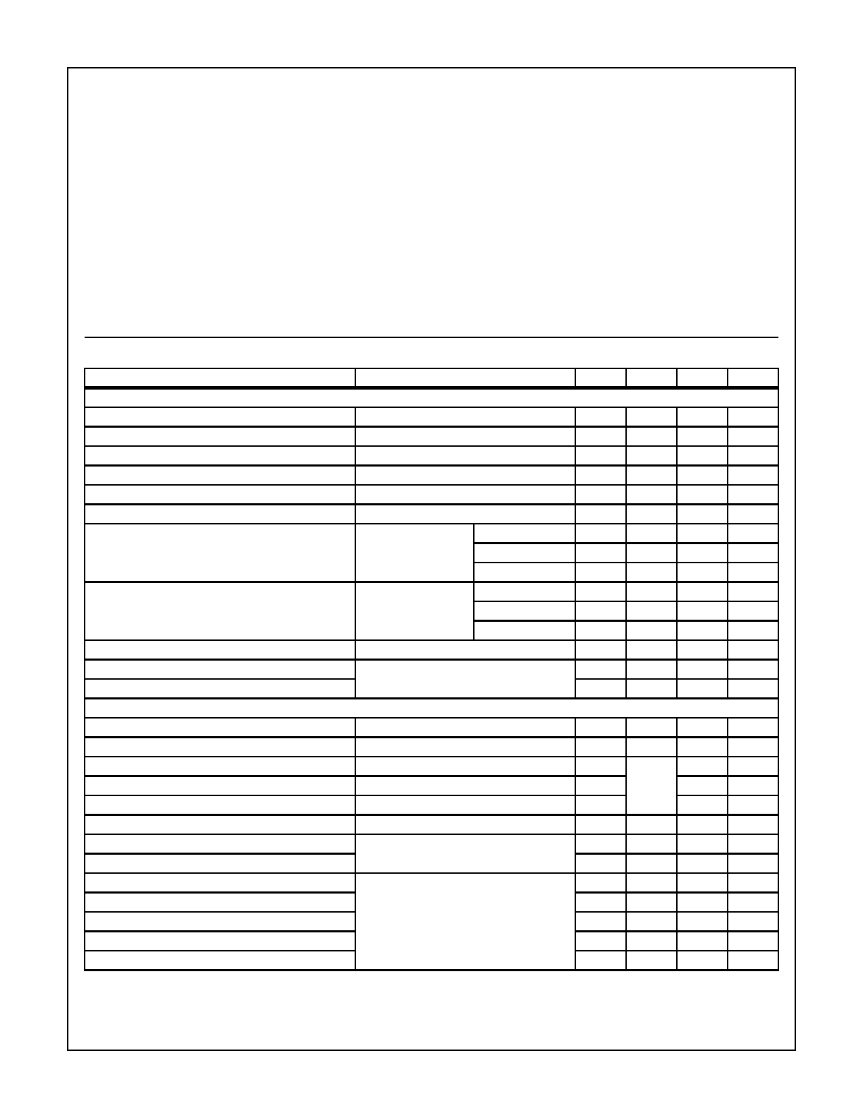
Electrical Specifications T
A
= 25
o
C
PARAMETER TEST CONDITIONS MIN TYP MAX UNITS
DC CHARACTERISTICS (For Each Transistor)
Collector-to-Base Breakdown Voltage I
C
= 10µA, I
E
= 0 20 32 - V
Collector-to-Emitter Breakdown Voltage I
C
= 1mA, I
B
= 0 15 24 - V
Collector-to-Substrate Breakdown-Voltage I
C1
= 10µA, I
B
= 0, I
E
= 0 20 60 - V
Emitter-to-Base Breakdown Voltage (Note 3) I
E
= 10µA, I
C
= 0 4 5.7 - V
Collector-Cutoff-Current V
CE
= 10V I
B
= 0 - - 0.5 µA
Collector-Cutoff-Current V
CB
= 10V, I
E
= 0 - - 40 nA
DC Forward-Current Transfer Ratio V
CE
= 6V I
C
= 5mA 35 88 -
I
C
= 1mA 40 90 -
I
C
= 0.1mA 35 85 -
Base-to-Emitter Voltage V
CE
= 6V I
C
= 5mA 0.71 0.81 0.91 V
I
C
= 1mA 0.66 0.76 0.86 V
I
C
= 0.1mA 0.60 0.70 0.80 V
Collector-to-Emitter Saturation Voltage I
C
= 10mA, I
B
= 1mA - 0.26 0.50 V
Magnitude of Difference in V
BE
Q
1
and Q
2
Matched
V
CE
= 6V, I
C
= 1mA
- 0.5 5 mV
Magnitude of Difference in I
B
- 0.2 3 µA
DYNAMIC CHARACTERISTICS
Noise Figure f = 100kHz, R
S
= 500Ω, I
C
= 1mA - 2.2 - dB
Gain-Bandwidth Product V
CE
= 6V, I
C
= 5mA - 1.15 - GHz
Collector-to-Base Capacitance V
CB
= 6V, f = 1MHz - See
Fig. 5
-pF
Collector-to-Substrate Capacitance V
CI
= 6V, f = 1MHz - - pF
Emitter-to-Base Capacitance V
BE
= 4V, f = 1MHz - - pF
Voltage Gain V
CE
= 6V, f = 10MHz, R
L
= 1kΩ, I
C
= 1mA - 28 - dB
Power Gain Cascode Configuration
f = 100MHz, V+ = 12V, I
C
= 1mA
27 30 - dB
Noise Figure - 3.5 - dB
Input Resistance Common-Emitter Configuration
V
CE
= 6V, I
C
= 1mA, f = 200 MHz
- 400 - Ω
Output Resistance - 4.6 - kΩ
Input Capacitance - 3.7 - pF
Output Capacitance -2-pF
Magnitude of Forward Transadmittance - 24 - mS
NOTE:
3. When used as a zener for reference voltage, the device must not be subjected to more than 0.1mJ of energy from any possible capacitance
or electrostatic discharge in order to prevent degradation of the junction. Maximum operating zener current should be less than 10mA.


