Second Difference (
∆
2
V)
Second difference is a Unitrode proprietary algorithm
that accumulates the difference between successive sam
-
ples of V
BAT
. The bq2031 takes a sample and makes a
termination decision at a frequency equal to 0.008
*
t
MTO
. Fast charge terminates when the accumulated dif
-
ference is
≤
-8mV. Second difference is used only in the
Two-Step Current algorithm, and is subject to a hold-off
period (see below).
Maximum Voltage
Fast charge terminates when V
CELL
≥
V
BLK
.V
BLK
is set
per equation 2. Maximum voltage is used for fast charge
termination in the Two-Step Current and Pulsed Cur
-
rent algorithms, and for transition from phase 1 to
phase 2 in the Two-Step Voltage algorithm. This crite
-
rion is subject to a hold-off period.
Hold-off Periods
Maximum V and
∆
2
V termination criteria are subject
to a hold-off period at the start of fast charge equal to
0.15
*
t
MTO
. During this time, these termination criteria
are ignored.
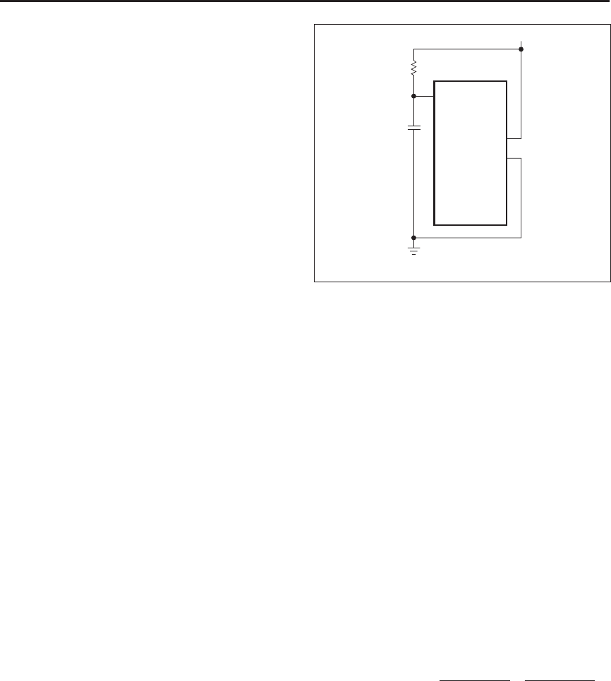
Maximum Time-Out
Fast charge terminates if the programmed MTO time is
reached without some other termination shutting off
fast charge. MTO is programmed from 1 to 24 hours by
an R-C network on TMTO (see Figure 9) per the equa-
tion:
Equation 6
t
MTO
= 0.5
*
R
*
C
where R is in k
Ω
, C is in
µ
F, and t
MTO
is in hours. Typi
-
cally, the maximum value for C of 0.1
µ
F is used.
Fast-charge termination by MTO is a Fault only in the
Pulsed Current algorithm; the bq2031 enters the Fault
state and waits for a new battery insertion, at which
time it begins a new charge cycle. In the Two-Step Volt
-
age and Two-Step Current algorithms, the bq2031 tran
-
sitions to the maintenance phase on MTO time-out.
The MTO timer starts at the beginning of fast charge. In
the Two-Step Voltage algorithm, it is cleared and re
-
started when the bq2031 transitions from phase 1 (cur
-
rent regulation) to phase 2 (voltage regulation). The
MTO timer is suspended (but not reset) during the out-
of-range temperature (Charge Pending) state.
Maintenance Charging
Three algorithms are used in maintenance charging:
n Two-Step Voltage algorithm
n
Two-Step Current algorithm
n
Pulsed Current algorithm
Two-Step Voltage Algorithm
In the Two-Step Voltage algorithm, the bq2031 provides
charge maintenance by regulating charging voltage to
V
FLT
. Charge current during maintenance is limited to
I
COND
.
Two-Step Current Algorithm
Maintenance charging in the Two-Step Current Algo
-
rithm is implemented by varying the period (T
P
)ofa
fixed current (I
COND
=I
MAX
/5) and duration (0.2 sec
-
onds) pulse to achieve the configured average mainte
-
nance current value. See Figure 10.
Maintenance current can be calculated by:
Equation 7
Maintenance current
I
T
I
T
COND
P
MAX
P
=
∗
=
∗(( . ) ) (( . ) )02 004
where T
P
is the period of the waveform in seconds.
Table 4 gives the values of P programmed by IGSEL.
9
bq2031
TM
FG203112.eps
V
CC
V
SS
bq2031
12
13
1
V
SS
V
CC
C
R
Figure 9. R-C Network for Setting MTO


