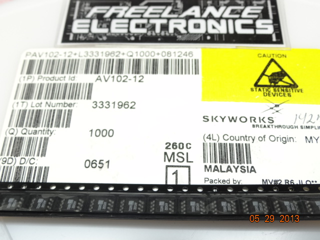
Freelance Electronics Components Distributor
Closed Dec 25th-26th
800-300-1968
We Stock Hard to Find Parts

AV102-12

Part # AV102-12
Description ATTENUATOR VARIABLE CURRENT 130 dB 800 MHZ SOIC-8
Category IC
Availability In Stock
Qty 848
Qty Price
1 - 41 $3.65835
42 - 103 $2.91005
104 - 200 $2.74377
201 - 303 $2.54976
304 + $2.27261
Manufacturer Available Qty
SKYWORKS
Date Code: 0651
  • Shipping Freelance Stock: 848
    Ships Immediately


Technical Document


DISCLAIMER: The information provided herein is solely for informational purposes. Customers must be aware of the suitability of this product for their application, and consider that variable factors such as Manufacturer, Product Category, Date Codes, Pictures and Descriptions may differ from available inventory.

Alpha Industries, Inc. [781] 935-5150 Fax [617] 824-4579 Email sales@alphaind.com www.alphaind.com 1
Specifications subject to change without notice. 6/01A
HIP3™ Variable Attenuator
1.70–2.00 GHz
Features
+50 dBm IP3 Typical
Low Loss 1 dB Typical
Attenuation 30 dB Typical
Good VSWR <1.5:1 Typical
Small SOIC-8 Package
AV102-12
Description
The AV102-12 is a current controlled variable attenuator
from Alpha’s series of HIP3™ components. It is designed
to meet the wide dynamic range required in spread
spectrum wireless base station applications. A monolithic
quadrature hybrid is teamed with a silicon PIN diode pair
in a plastic surface mount package reducing size and
assuring consistency from part to part.
Parameter Min. Typ. Max. Unit
Frequency 1.70 2.00 GHz
Insertion Loss (0 mA Control Current) 1 1.5 dB
Attenuation @ 3.0 mA Control Current (1850 MHz) 18.5 25.0 dB
VSWR All Ports 1.5 1.8
Input 3rd Order Intercept +47 +50 dBm
Group Delay 0.6 1.0 ns
Electrical Specifications at 25°C
Parameter
1
Condition Frequency Min. Typ. Max. Unit
Switching Characteristics
2
Rise, Fall (10/90% or 90/10% RF) 5 µs
On, Off (50% CTL to 90/10% RF) 8 µs
Video Feedthru (Peak) 2 mV
Maximum Input Power for <1 dB
Attenuation Variation +15 dBm
Operating Characteristics at 25°C (0, +5 V)
1. All measurements made in a 50 system, unless otherwise specified.
2. 0–4 mA square wave total control current.
2 Alpha Industries, Inc. [781] 935-5150 Fax [617] 824-4579 Email sales@alphaind.com www.alphaind.com
Specifications subject to change without notice. 6/01A
HIP3™ Variable Attenuator 1.70–2.00 GHz AV102-12
VSWR (:1)
Input/Output VSWR vs. Current
@ 1700 MHz
1.0
1.1
1.2
1.3
1.4
1.5
0.0000 0.0010 0.0020 0.0030 0.0040 0.0050
Current (Amps)
Input
Output
VSWR (:1)
Input/Output VSWR vs. Current
@ 1850 MHz
1.0
1.1
1.2
1.3
1.4
1.5
Current (Amps)
0.0000 0.0010 0.0020 0.0030 0.0040 0.0050
Input
Output
Attenuation (dB)
0.0000 0.0010 0.0020 0.0030 0.0040 0.0050
Attenuation vs. Current
-50.0
-40.0
-30.0
-20.0
-10.0
0.0
Current (Amps)
1850 MHz
2000 MHz
1700 MHz
Attenuation (dB)
1.70 1.80 1.90 2.00
Attenuation vs. Frequency
-25.0
-20.0
-15.0
-10.0
-5.0
0.0
Frequency (GHz)
0.0 mA
0.2 mA
0.7 mA
1.7 mA
2.4 mA
3.0 mA
Input/Output VSWR vs. Current
@ 2000 MHz
1.0
1.1
1.2
1.3
1.4
1.5
Current (Amps)
VSWR (:1)
0.0000 0.0010 0.0020 0.0030 0.0040 0.0050
Input
Output
Diode Current (mA)
400 600 800 1000
Typical PIN Diode Current vs. Voltage
0.01
0.1
1
10
Diode Voltage (mV)
Typical Performance Data
HIP3 Variable Attenuator 1.702.00 GHz AV102-12
Alpha Industries, Inc. [781] 935-5150 Fax [617] 824-4579 Email sales@alphaind.com www.alphaind.com 3
Specifications subject to change without notice. 6/01A
Characteristic Value
RF Input Power .5 W CW, 4 W @ 12.5%
Duty Cycle
Control Current 50 mA Each Diode
Operating Temperature -40 to +85°C
Storage Temperature -40 to +85°C
Maximum Reverse Diode Voltage -10 V
Electrostatic Discharge +125 V
Absolute Maximum Ratings
Note: Operating this device above any of these parameters may cause
irreversible damage.
Recommended Board Layout
0.1630
0.0200 DIA.
VIA 4 PLACES
0.0190 TYP.0.0555 TYP.
SOIC-8
0.049
(1.24 mm)
0.016
(0.41 mm)
0.016 MAX.
(0.41 mm) x
45˚ CHAMFER
PIN 1
0.197 (5.00 mm)
0.189 (4.80 mm)
0.068
(1.73 mm) MAX.
0.010 (0.25 mm)
0.004 (0.10 mm)
0.010 (0.25 mm)
0.007 (0.17 mm)
0.158 (4.00 mm)
0.150 (3.80 mm)
MAX.
0.020 (0.51 mm) MAX.
0.244 (6.20 mm)
0.228 (5.80 mm)
0.050 (1.27 mm) BSC
PIN 8
PIN 1
INDICATOR
1234
CONTROL
CURRENT
GND
220 pF
RF In
GND
680
8765
GND
220 pF
100 nH 100 nH
RF Out
CONTROL
CURRENT
GND
Pin Out
CONTROL
CURRENT
CONTROL
CURRENT
RF OUT
RF IN
Connection Diagram
Material is 10 mil FR4.