Freelance Electronics Components Distributor
Closed Dec 25th-26th
800-300-1968
We Stock Hard to Find Parts

ATMEGA48-20AU

Part # ATMEGA48-20AU
Description MCU 8BIT ATMEGA RISC 4KB FLASH 3.3V/5V 32TQFP - Trays
Category IC
Availability Out of Stock
Qty 0
Qty Price
1 + $1.49230


Technical Document


DISCLAIMER: The information provided herein is solely for informational purposes. Customers must be aware of the suitability of this product for their application, and consider that variable factors such as Manufacturer, Product Category, Date Codes, Pictures and Descriptions may differ from available inventory.

259
2545M–AVR–09/07
ATmega48/88/168
23.8.3 ADCL and ADCH – The ADC Data Register
23.8.3.1 ADLAR = 0
23.8.3.2 ADLAR = 1
When an ADC conversion is complete, the result is found in these two registers.
When ADCL is read, the ADC Data Register is not updated until ADCH is read. Consequently, if
the result is left adjusted and no more than 8-bit precision is required, it is sufficient to read
ADCH. Otherwise, ADCL must be read first, then ADCH.
The ADLAR bit in ADMUX, and the MUXn bits in ADMUX affect the way the result is read from
the registers. If ADLAR is set, the result is left adjusted. If ADLAR is cleared (default), the result
is right adjusted.
ADC9:0: ADC Conversion Result
These bits represent the result from the conversion, as detailed in “ADC Conversion Result” on
page 256.
23.8.4 ADCSRB – ADC Control and Status Register B
Bit 7, 5:3 – Res: Reserved Bits
These bits are reserved for future use. To ensure compatibility with future devices, these bist
must be written to zero when ADCSRB is written.
Bit 2:0 – ADTS2:0: ADC Auto Trigger Source
If ADATE in ADCSRA is written to one, the value of these bits selects which source will trigger
an ADC conversion. If ADATE is cleared, the ADTS2:0 settings will have no effect. A conversion
will be triggered by the rising edge of the selected Interrupt Flag. Note that switching from a trig-
ger source that is cleared to a trigger source that is set, will generate a positive edge on the
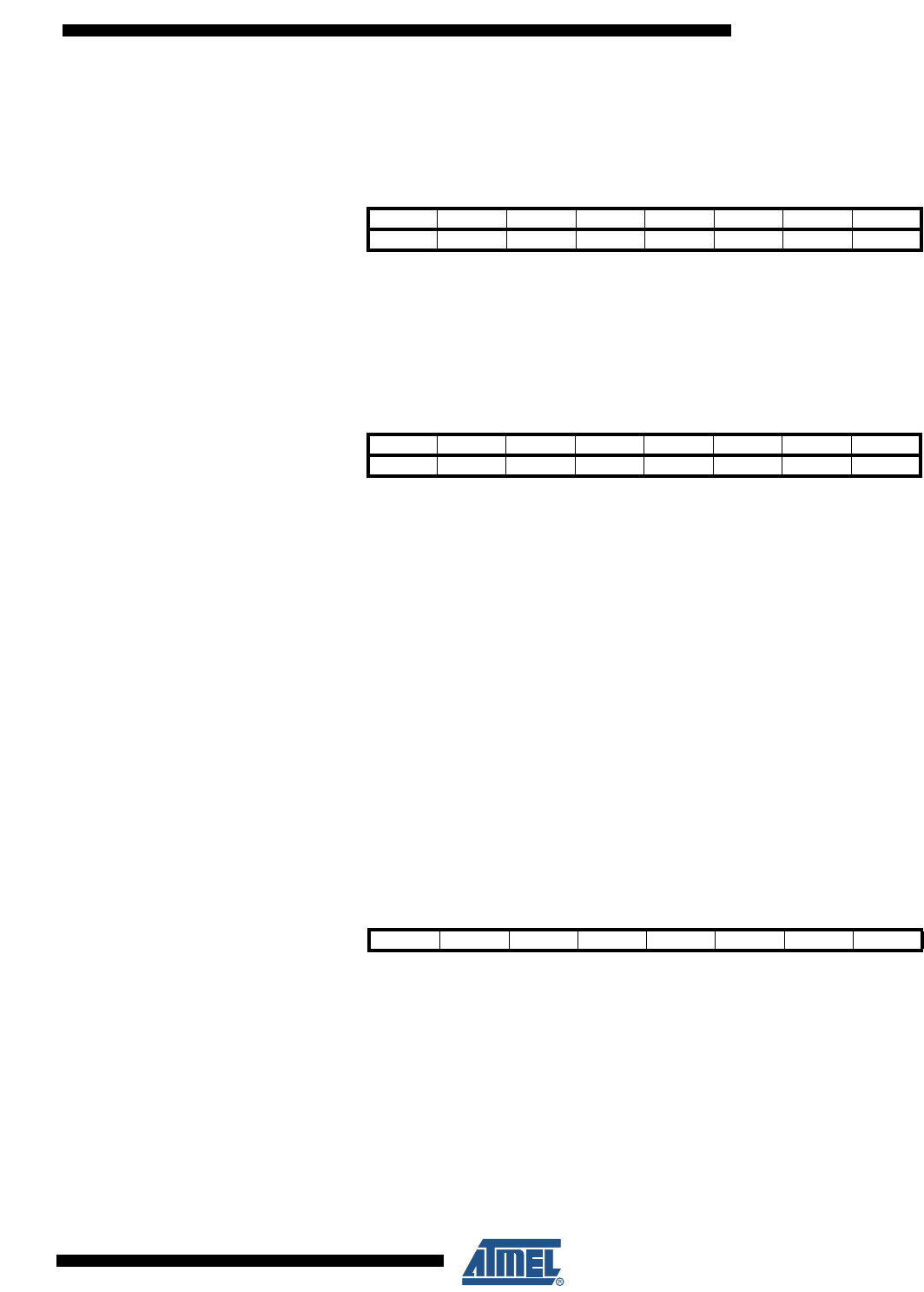
Bit 151413121110 9 8
(0x79) ––––––ADC9 ADC8 ADCH
(0x78) ADC7 ADC6 ADC5 ADC4 ADC3 ADC2 ADC1 ADC0 ADCL
76543210
Read/Write RRRRRRRR
RRRRRRRR
Initial Value00000000
00000000
Bit 151413121110 9 8
(0x79) ADC9 ADC8 ADC7 ADC6 ADC5 ADC4 ADC3 ADC2 ADCH
(0x78) ADC1 ADC0 ––––ADCL
76543210
Read/Write RRRRRRRR
RRRRRRRR
Initial Value00000000
00000000
Bit 76543210
(0x7B) ACME ADTS2 ADTS1 ADTS0 ADCSRB
Read/Write R R/W R R R R/W R/W R/W
Initial Value00000000
260
2545M–AVR–09/07
ATmega48/88/168
trigger signal. If ADEN in ADCSRA is set, this will start a conversion. Switching to Free Running
mode (ADTS[2:0]=0) will not cause a trigger event, even if the ADC Interrupt Flag is set
.
23.8.5 DIDR0 – Digital Input Disable Register 0
Bits 7:6 – Res: Reserved Bits
These bits are reserved for future use. To ensure compatibility with future devices, these bits
must be written to zero when DIDR0 is written.
Bit 5:0 – ADC5D..ADC0D: ADC5..0 Digital Input Disable
When this bit is written logic one, the digital input buffer on the corresponding ADC pin is dis-
abled. The corresponding PIN Register bit will always read as zero when this bit is set. When an
analog signal is applied to the ADC5..0 pin and the digital input from this pin is not needed, this
bit should be written logic one to reduce power consumption in the digital input buffer.
Note that ADC pins ADC7 and ADC6 do not have digital input buffers, and therefore do not
require Digital Input Disable bits.
Table 23-5. ADC Auto Trigger Source Selections
ADTS2 ADTS1 ADTS0 Trigger Source
0 0 0 Free Running mode
0 0 1 Analog Comparator
0 1 0 External Interrupt Request 0
0 1 1 Timer/Counter0 Compare Match A
1 0 0 Timer/Counter0 Overflow
1 0 1 Timer/Counter1 Compare Match B
1 1 0 Timer/Counter1 Overflow
1 1 1 Timer/Counter1 Capture Event
Bit 76543210
(0x7E) ADC5D ADC4D ADC3D ADC2D ADC1D ADC0D DIDR0
Read/Write R R R/W R/W R/W R/W R/W R/W
Initial Value 0 0 0 0 0 0 0 0
261
2545M–AVR–09/07
ATmega48/88/168
24. debugWIRE On-chip Debug System
24.1 Features
Complete Program Flow Control
Emulates All On-chip Functions, Both Digital and Analog, except RESET Pin
Real-time Operation
Symbolic Debugging Support (Both at C and Assembler Source Level, or for Other HLLs)
Unlimited Number of Program Break Points (Using Software Break Points)
Non-intrusive Operation
Electrical Characteristics Identical to Real Device
Automatic Configuration System
High-Speed Operation
Programming of Non-volatile Memories
24.2 Overview
The debugWIRE On-chip debug system uses a One-wire, bi-directional interface to control the
program flow, execute AVR instructions in the CPU and to program the different non-volatile
memories.
24.3 Physical Interface
When the debugWIRE Enable (DWEN) Fuse is programmed and Lock bits are unprogrammed,
the debugWIRE system within the target device is activated. The RESET port pin is configured
as a wire-AND (open-drain) bi-directional I/O pin with pull-up enabled and becomes the commu-
nication gateway between target and emulator.
Figure 24-1. The debugWIRE Setup
Figure 24-1 shows the schematic of a target MCU, with debugWIRE enabled, and the emulator
connector. The system clock is not affected by debugWIRE and will always be the clock source
selected by the CKSEL Fuses.
d
W
GND
dW(RESET)
VCC
1.8 - 5.5
V
PREVIOUS8081828384858687888990919293NEXT