Freelance Electronics Components Distributor
Closed Dec 25th-26th
800-300-1968
We Stock Hard to Find Parts

ATMEGA48-20AU

Part # ATMEGA48-20AU
Description MCU 8BIT ATMEGA RISC 4KB FLASH 3.3V/5V 32TQFP - Trays
Category IC
Availability Out of Stock
Qty 0
Qty Price
1 + $1.49230


Technical Document


DISCLAIMER: The information provided herein is solely for informational purposes. Customers must be aware of the suitability of this product for their application, and consider that variable factors such as Manufacturer, Product Category, Date Codes, Pictures and Descriptions may differ from available inventory.

211
2545M–AVR–09/07
ATmega48/88/168
The PRTWI bit in “Minimizing Power Consumption” on page 42 must be written to zero to enable
the 2-wire Serial Interface.
21.2.2 Electrical Interconnection
As depicted in Figure 21-1, both bus lines are connected to the positive supply voltage through
pull-up resistors. The bus drivers of all TWI-compliant devices are open-drain or open-collector.
This implements a wired-AND function which is essential to the operation of the interface. A low
level on a TWI bus line is generated when one or more TWI devices output a zero. A high level
is output when all TWI devices tri-state their outputs, allowing the pull-up resistors to pull the line
high. Note that all AVR devices connected to the TWI bus must be powered in order to allow any
bus operation.
The number of devices that can be connected to the bus is only limited by the bus capacitance
limit of 400 pF and the 7-bit slave address space. A detailed specification of the electrical char-
acteristics of the TWI is given in “2-wire Serial Interface Characteristics” on page 309. Two
different sets of specifications are presented there, one relevant for bus speeds below 100 kHz,
and one valid for bus speeds up to 400 kHz.
21.3 Data Transfer and Frame Format
21.3.1 Transferring Bits
Each data bit transferred on the TWI bus is accompanied by a pulse on the clock line. The level
of the data line must be stable when the clock line is high. The only exception to this rule is for
generating start and stop conditions.
Figure 21-2. Data Validity
21.3.2 START and STOP Conditions
The Master initiates and terminates a data transmission. The transmission is initiated when the
Master issues a START condition on the bus, and it is terminated when the Master issues a
STOP condition. Between a START and a STOP condition, the bus is considered busy, and no
Slave The device addressed by a Master.
Transmitter The device placing data on the bus.
Receiver The device reading data from the bus.
Table 21-1. TWI Terminology
Term Description
SDA
SCL
Data Stable Data Stable
Data Change
212
2545M–AVR–09/07
ATmega48/88/168
other master should try to seize control of the bus. A special case occurs when a new START
condition is issued between a START and STOP condition. This is referred to as a REPEATED
START condition, and is used when the Master wishes to initiate a new transfer without relin-
quishing control of the bus. After a REPEATED START, the bus is considered busy until the next
STOP. This is identical to the START behavior, and therefore START is used to describe both
START and REPEATED START for the remainder of this datasheet, unless otherwise noted. As
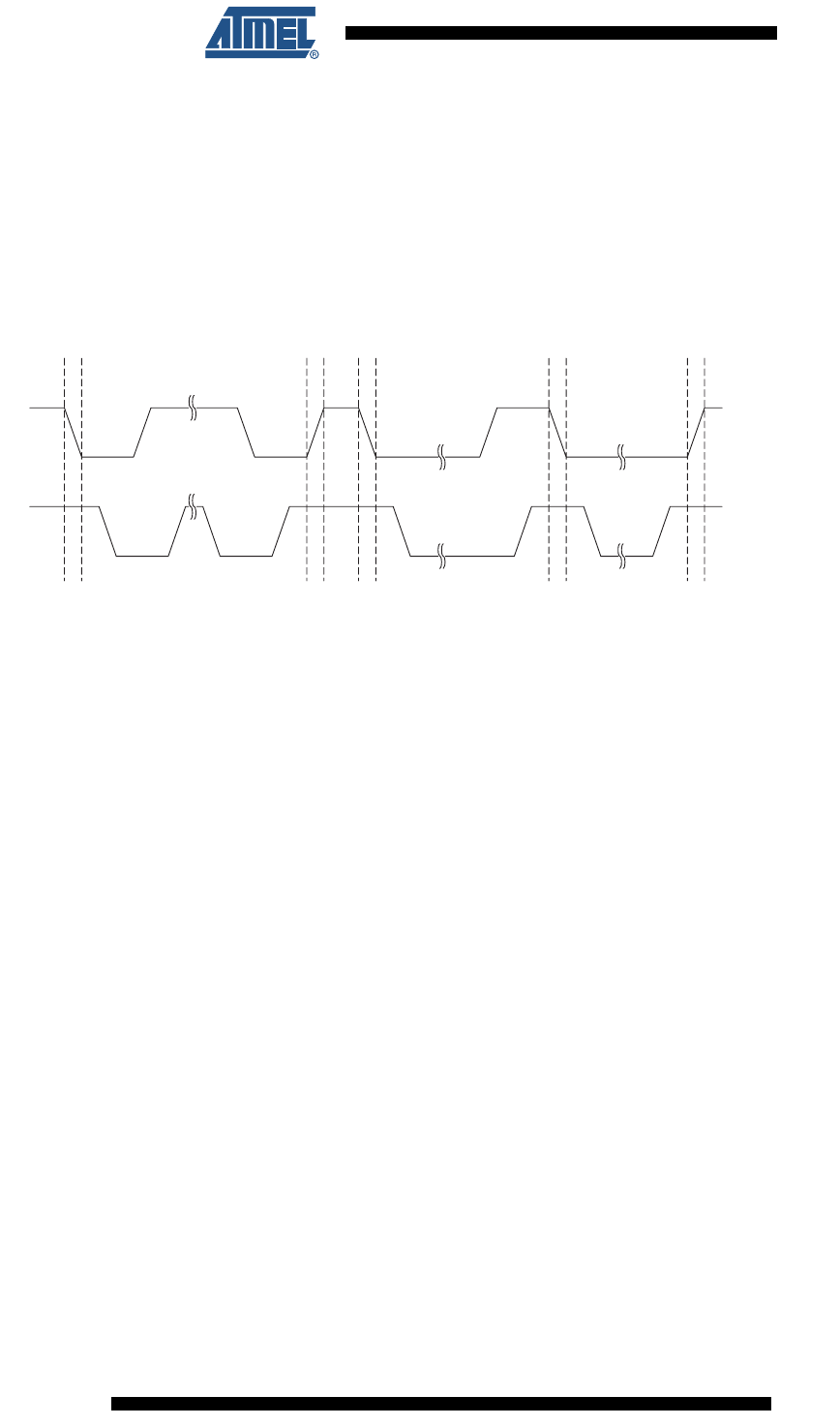
depicted below, START and STOP conditions are signalled by changing the level of the SDA
line when the SCL line is high.
Figure 21-3. START, REPEATED START and STOP conditions
21.3.3 Address Packet Format
All address packets transmitted on the TWI bus are 9 bits long, consisting of 7 address bits, one
READ/WRITE control bit and an acknowledge bit. If the READ/WRITE bit is set, a read opera-
tion is to be performed, otherwise a write operation should be performed. When a Slave
recognizes that it is being addressed, it should acknowledge by pulling SDA low in the ninth SCL
(ACK) cycle. If the addressed Slave is busy, or for some other reason can not service the Mas-
ter’s request, the SDA line should be left high in the ACK clock cycle. The Master can then
transmit a STOP condition, or a REPEATED START condition to initiate a new transmission. An
address packet consisting of a slave address and a READ or a WRITE bit is called SLA+R or
SLA+W, respectively.
The MSB of the address byte is transmitted first. Slave addresses can freely be allocated by the
designer, but the address 0000 000 is reserved for a general call.
When a general call is issued, all slaves should respond by pulling the SDA line low in the ACK
cycle. A general call is used when a Master wishes to transmit the same message to several
slaves in the system. When the general call address followed by a Write bit is transmitted on the
bus, all slaves set up to acknowledge the general call will pull the SDA line low in the ack cycle.
The following data packets will then be received by all the slaves that acknowledged the general
call. Note that transmitting the general call address followed by a Read bit is meaningless, as
this would cause contention if several slaves started transmitting different data.
All addresses of the format 1111 xxx should be reserved for future purposes.
SDA
SCL
START STOPREPEATED START
STOP START
213
2545M–AVR–09/07
ATmega48/88/168
Figure 21-4. Address Packet Format
21.3.4 Data Packet Format
All data packets transmitted on the TWI bus are nine bits long, consisting of one data byte and
an acknowledge bit. During a data transfer, the Master generates the clock and the START and
STOP conditions, while the Receiver is responsible for acknowledging the reception. An
Acknowledge (ACK) is signalled by the Receiver pulling the SDA line low during the ninth SCL
cycle. If the Receiver leaves the SDA line high, a NACK is signalled. When the Receiver has
received the last byte, or for some reason cannot receive any more bytes, it should inform the
Transmitter by sending a NACK after the final byte. The MSB of the data byte is transmitted first.
Figure 21-5. Data Packet Format
21.3.5 Combining Address and Data Packets into a Transmission
A transmission basically consists of a START condition, a SLA+R/W, one or more data packets
and a STOP condition. An empty message, consisting of a START followed by a STOP condi-
tion, is illegal. Note that the Wired-ANDing of the SCL line can be used to implement
handshaking between the Master and the Slave. The Slave can extend the SCL low period by
pulling the SCL line low. This is useful if the clock speed set up by the Master is too fast for the
Slave, or the Slave needs extra time for processing between the data transmissions. The Slave
extending the SCL low period will not affect the SCL high period, which is determined by the
Master. As a consequence, the Slave can reduce the TWI data transfer speed by prolonging the
SCL duty cycle.
Figure 21-6 shows a typical data transmission. Note that several data bytes can be transmitted
between the SLA+R/W and the STOP condition, depending on the software protocol imple-
mented by the application software.
SDA
SCL
START
12 789
Addr MSB Addr LSB R/W
ACK
12 789
Data MSB Data LSB ACK
Aggregate
SDA
SDA from
Transmitter
SDA from
Receiver
SCL from
Master
SLA+R/W Data Byte
STOP, REPEATED
START or Next
Data Byte
PREVIOUS6465666768697071727374757677NEXT