Freelance Electronics Components Distributor
Closed Dec 25th-26th
800-300-1968
We Stock Hard to Find Parts

ATMEGA48-20AU

Part # ATMEGA48-20AU
Description MCU 8BIT ATMEGA RISC 4KB FLASH 3.3V/5V 32TQFP - Trays
Category IC
Availability Out of Stock
Qty 0
Qty Price
1 + $1.49230


Technical Document


DISCLAIMER: The information provided herein is solely for informational purposes. Customers must be aware of the suitability of this product for their application, and consider that variable factors such as Manufacturer, Product Category, Date Codes, Pictures and Descriptions may differ from available inventory.

322
2545M–AVR–09/07
ATmega48/88/168
Figure 29-12. Idle Supply Current vs. V
CC
(32 kHz External Oscillator)
29.3 Supply Current of I/O modules
The tables and formulas below can be used to calculate the additional current consumption for
the different I/O modules in Active and Idle mode. The enabling or disabling of the I/O modules
are controlled by the Power Reduction Register. See “Power Reduction Register” on page 42 for
details.
IDLE SUPPLY CURRENT vs. V
CC
32 kHz EXTERNAL OSCILLATOR
25 °C
0
5
10
15
20
25
30
1.5 2 2.5 3 3.5 4 4.5 5 5.5
V
CC
(V)
I
CC
(uA)
Table 29-1. Additional Current Consumption for the different I/O modules (absolute values)
PRR bit Typical numbers
V
CC
= 2V, F = 1MHz V
CC
= 3V, F = 4MHz V
CC
= 5V, F = 8MHz
PRUSART0 8.0 uA 51 uA 220 uA
PRTWI 12 uA 75 uA 315 uA
PRTIM2 11 uA 72 uA 300 uA
PRTIM1 5.0 uA 32 uA 130 uA
PRTIM0 4.0 uA 24 uA 100 uA
PRSPI 15 uA 95 uA 400 uA
PRADC 12 uA 75 uA 315 uA
323
2545M–AVR–09/07
ATmega48/88/168
It is possible to calculate the typical current consumption based on the numbers from Table 2 for
other V
CC
and frequency settings than listed in Table 1.
29.3.0.1 Example 1
Calculate the expected current consumption in idle mode with USART0, TIMER1, and TWI
enabled at V
CC
= 3.0V and F = 1MHz. From Table 2, third column, we see that we need to add
18% for the USART0, 26% for the TWI, and 11% for the TIMER1 module. Reading from Figure
3, we find that the idle current consumption is ~0,075mA at V
CC
= 3.0V and F = 1MHz. The total
current consumption in idle mode with USART0, TIMER1, and TWI enabled, gives:
29.3.0.2 Example 2
Same conditions as in example 1, but in active mode instead. From Table 2, second column we
see that we need to add 3.3% for the USART0, 4.8% for the TWI, and 2.0% for the TIMER1
module. Reading from Figure 1, we find that the active current consumption is ~0,42mA at V
CC
=
3.0V and F = 1MHz. The total current consumption in idle mode with USART0, TIMER1, and
TWI enabled, gives:
29.3.0.3 Example 3
All I/O modules should be enabled. Calculate the expected current consumption in active mode
at V
CC
= 3.6V and F = 10MHz. We find the active current consumption without the I/O modules
to be ~ 4.0mA (from Figure 2). Then, by using the numbers from Table 2 - second column, we
find the total current consumption:
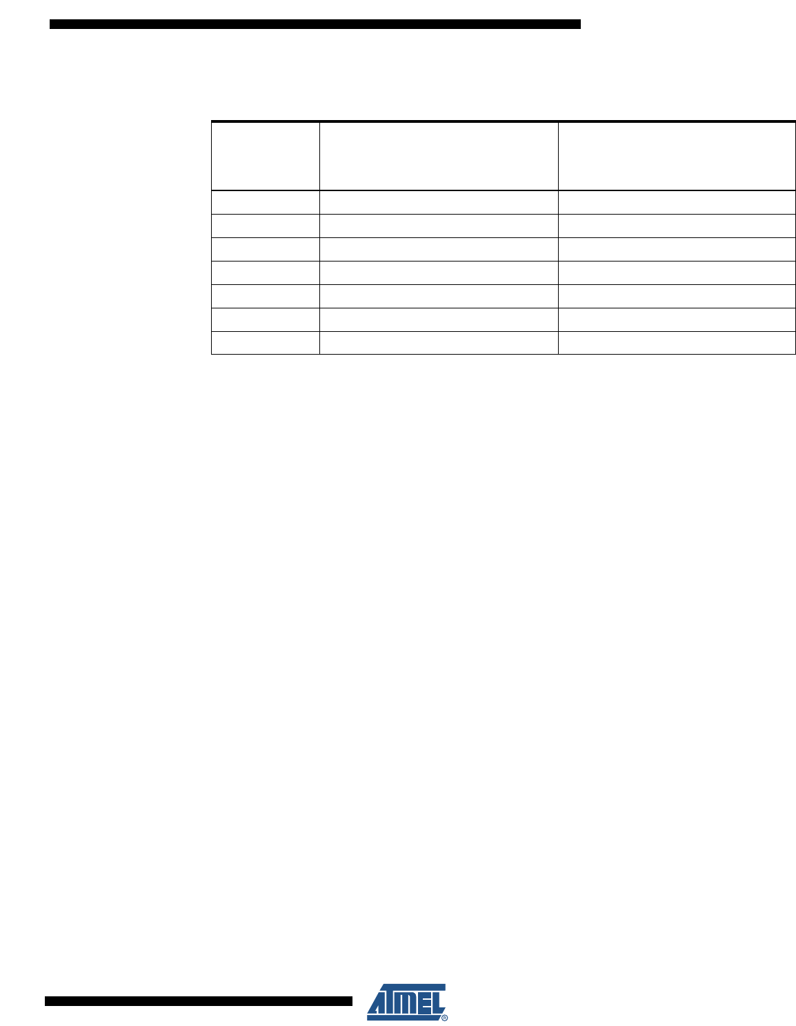
Table 29-2. Additional Current Consumption (percentage) in Active and Idle mode
PRR bit
Additional Current consumption
compared to Active with external
clock
(see Figure 29-1 and Figure 29-2)
Additional Current consumption
compared to Idle with external clock
(see Figure 29-7 and Figure 29-8)
PRUSART0 3.3% 18%
PRTWI 4.8% 26%
PRTIM2 4.7% 25%
PRTIM1 2.0% 11%
PRTIM0 1.6% 8.5%
PRSPI 6.1% 33%
PRADC 4.9% 26%
ICCtotal
0,075
mA
10,180,260,11+++
()
0,116
mA≈≈
I
CCtotal
0,42
mA
1 0,033 0,048 0,02+++
()
0,46
mA≈≈
I
CCtotal
4,0
mA
1 0,033 0,048 0,047 0,02 0,016 0,061 0,049+++++++
()
5,1
mA≈≈
324
2545M–AVR–09/07
ATmega48/88/168
29.4 Power-Down Supply Current
Figure 29-13. Power-Down Supply Current vs. V
CC
(Watchdog Timer Disabled)
Figure 29-14. Power-Down Supply Current vs. V
CC
(Watchdog Timer Enabled)
POWER-DOWN SUPPLY CURRENT vs. V
CC
WATCHDOG TIMER DISABLED
85 °C
25 °C
-40 °C
0
0.5
1
1.5
2
2.5
1.5 2 2.5 3 3.5 4 4.5 5 5.5
V
CC
(V)
I
CC
(uA)
POWER-DOWN SUPPLY CURRENT vs. V
CC
WATCHDOG TIMER ENABLED
85 °C
25 °C
-40 °C
0
2
4
6
8
10
12
1.5 2 2.5 3 3.5 4 4.5 5 5.5
V
CC
(V)
I
CC
(uA)
PREVIOUS101102103104105106107108109110111112113114NEXT