Freelance Electronics Components Distributor
Closed Dec 25th-26th
800-300-1968
We Stock Hard to Find Parts

AT84AD001BITD

Part # AT84AD001BITD
Description ADC DUAL FLASH 1GSPS 8BIT PARALLEL 144LQFP - Trays
Category IC
Availability Out of Stock
Qty 0
Qty Price
1 + $154.41500


Technical Document


DISCLAIMER: The information provided herein is solely for informational purposes. Customers must be aware of the suitability of this product for their application, and consider that variable factors such as Manufacturer, Product Category, Date Codes, Pictures and Descriptions may differ from available inventory.

22
AT84AD001B
2153C–BDC–04/04
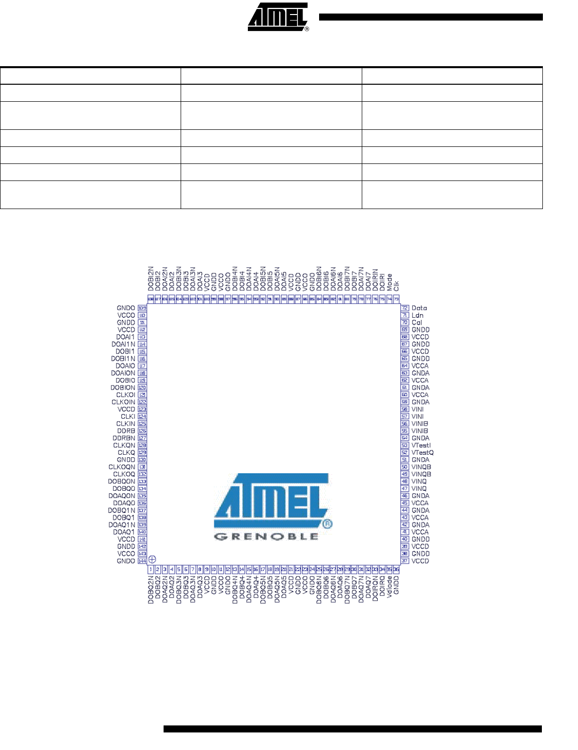
Figure 14. AT84AD001B Pinout (Top View)
CLKOIN 122 Inverted phase (-) output clock channel I
CLKOQ 132
Output clock in-phase (+) channel Q,
1/2 input clock frequency
CLKOQN 131 Inverted phase (-) output clock channel Q
VtestQ, VtestI 52, 53 Pins for internal test (to be left open)
Cal 70 Calibration output bit status
Vdiode 35
Positive node of diode used for die
junction temperature measurements
Table 10. AT84AD001B LQFP 144 Pin Description (Continued)
Symbol Pin number Function
LQFP 144
20 by 20 by 1.4 mm
Atmel - Dual 8-bit
23
AT84AD001B
2153C–BDC–04/04
Typical Characterization Results
Nominal conditions (unless otherwise specified):
•V
CCA
= 3.3V; V
CCD
= 3.3V; V
CCO
= 2.25V
•V
INI
- V
INB
or V
INQ
to V
INQB
= 500 mVpp full-scale differential input
LVDS digital outputs (100)
TA (typical) = 25° C
Full temperature range: 0
°C < TA < 70°C (commercial grade) or -40°C
< TA < 85° C (industrial grade)
Typical Full Power Input
Bandwidth
Fs = 500 Msps
Pclock = 0 dBm
•Pin = -1 dBFS
Gain flatness (±0.5 dB) from DC to > 500 MHz
Full power input bandwidth at -3 dB > 1.5 GHz
Figure 15. Full Power Input Bandwidth
-11
-10
-9
-8
-7
-6
-5
-4
-3
-2
-1
0
100 300 500 700 900 1100 1300 1500 1700 1900 2100 2300 2500 2700 2900
Fin (MHz)
dBFS
-3 dB Bandwidth
24
AT84AD001B
2153C–BDC–04/04
Typical Crosstalk Figure 16. Crosstalk (Fs = 500 Msps)
Note: Measured on the AT84AD001TD-EB Evaluation Board.
Typical DC, INL and DNL
Patterns
1:2 DMUX mode, Fs/4 DR type
Figure 17. Typical INL (Fs = 50 Msps, Fin = 1 MHz, Saturated Input)
0
10
20
30
40
50
60
70
80
0 100 200 300 400 500 600 700 800 900 1000
Fin (MHz)
dBc
-0,6
-0,4
-0,2
0
0,2
0,4
0,6
1 16 31 46 61 76 91 106 121 136 151 166 181 196 211 226 241 256
Codes
INL (Lsb)
PREVIOUS1234567891011121314NEXT